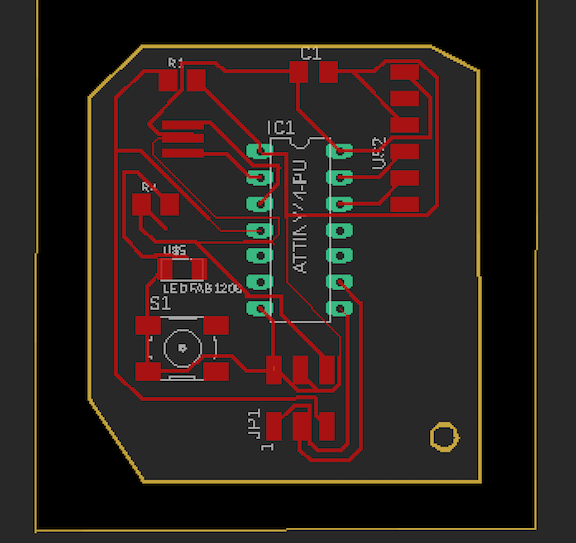
This week we were tasked with remaking Neil's hello-world board to include a button and LED, milling, soldering, and programming it, and then testing it usign a voltmeter and oscilloscope. I used EAGLE, an Autodesk software for designing PCBs, to design a board including all the parts on the hello-world schematic plus a button controlling current flow through an LED - the button and LED were superfluous to the board's operation in this design, since I wanted both components to be functional and troubleshooting to be as straightforward as possible. After designing the board in EAGLE, I created PNG files rendering the board's interior and exterior as black-and-white images to be sent to the milling machine using Neil's mods software.
I used the Roland SRM-20 located in the harvard science center to mill the board. Knowing that I'd had issues with cut depth during the USB PCB week, I proactively adjusted the cut depth in mods to 0.01 cm before making my first cut. Though I'd been importing cropped PNGs straight from EAGLE, my first several runs magnified the image beyond the scope of our fairly small blanks. I later learned that this was a problem other Mac OS users were experiencing, and we realized that doubling the dpi of the image in mods solved the problem.
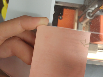
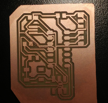
Above, a result of this sizing misjudgment: the mill begins at a point off of the board.
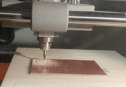
Milling in progress. My first fully milled board came out with its traces almost totally cut away. This may have been a result of the downscaling that I'd retroactively applied to the png, or, as Rob pointed out, I may not have exported the image with a high enough resolution (he recommended 1000 dpi).
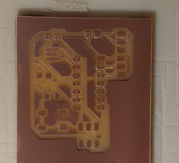
I redesigned the Eagle model with thicker traces (10mm) and rearranged it so that I got no overlap error messages. I sent this design to the mill and it came out looking promising. As I was checking it against the design I realized that many of the traces had merged and I tried to separate them with an X-acto knife. Unfortunately my hand was not precise enough to do this neatly but I thought I could perhaps bridge some pads with wires if these copper connections failed.
At this point Rob informed me that I'd used the wrong Attiny part from the fab library and I'd have to redesign in EAGLE to be able to fit one of our Attiny chips onto the board. This was as far as I got this week. I spent a lot of time learning how to use EAGLE and look forward to attaining greater fluency and ease with the software.