Assignment
-add an output device to a microcontroller board you've designed, and program it to do something
-measure the power consumption of an output device
Goal
Design a board that will output a variety of ‘rawwwrrrs.’Steps
1. Design a board that outputs sound, and specifically the future ability to output dinosaur ‘rawrs.’ I started in Eagle using Neil’s hello.speaker.45 example but changed out the power source to a 5V connector and adjusted the shape in anticipation of how to eventually fit the board in the belly of a dinosaur.2. The design in Eagle takes a bit of searching for the right components and then the majority of the time is spent routing the wires, but it’s somewhat meditative. And I love to get them all connected except for one and then start over! Because I am optimizing for size, I did not add a small dinosaur to the board, which just felt wrong, I may try to adjust the shape to mirror a dino for the next iteration.
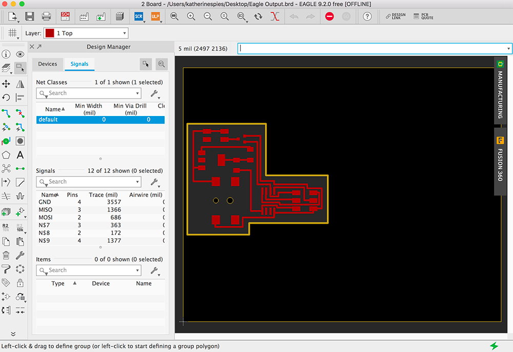
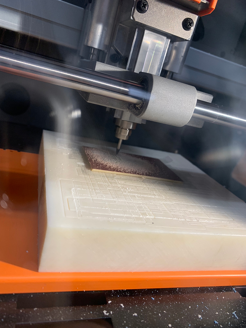
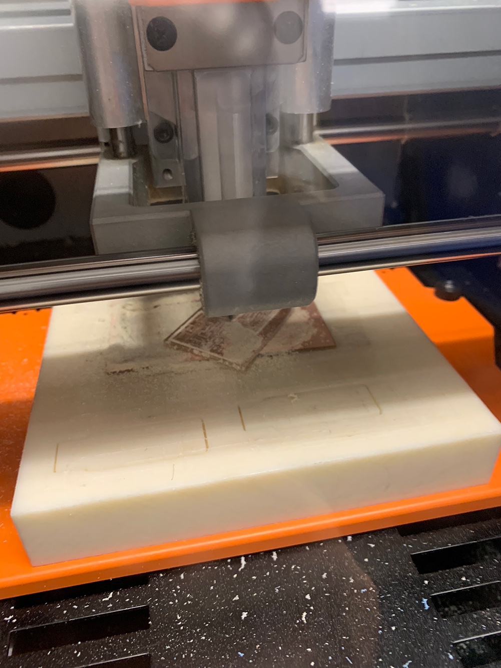
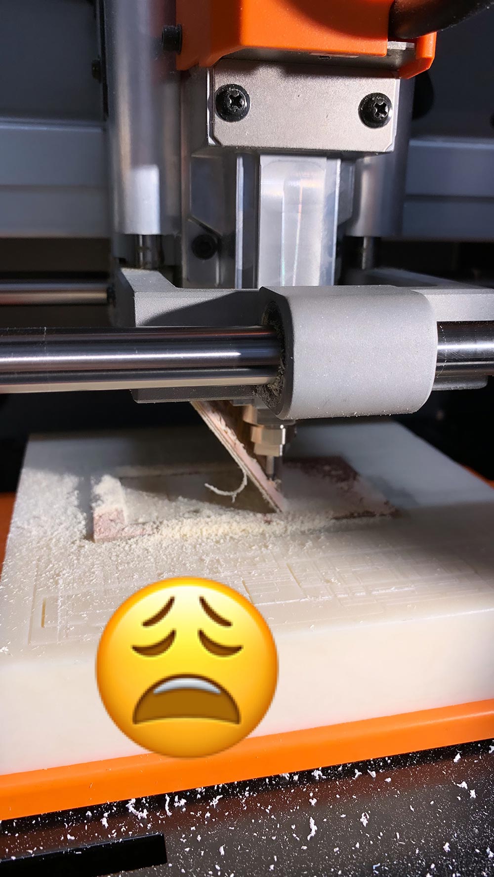
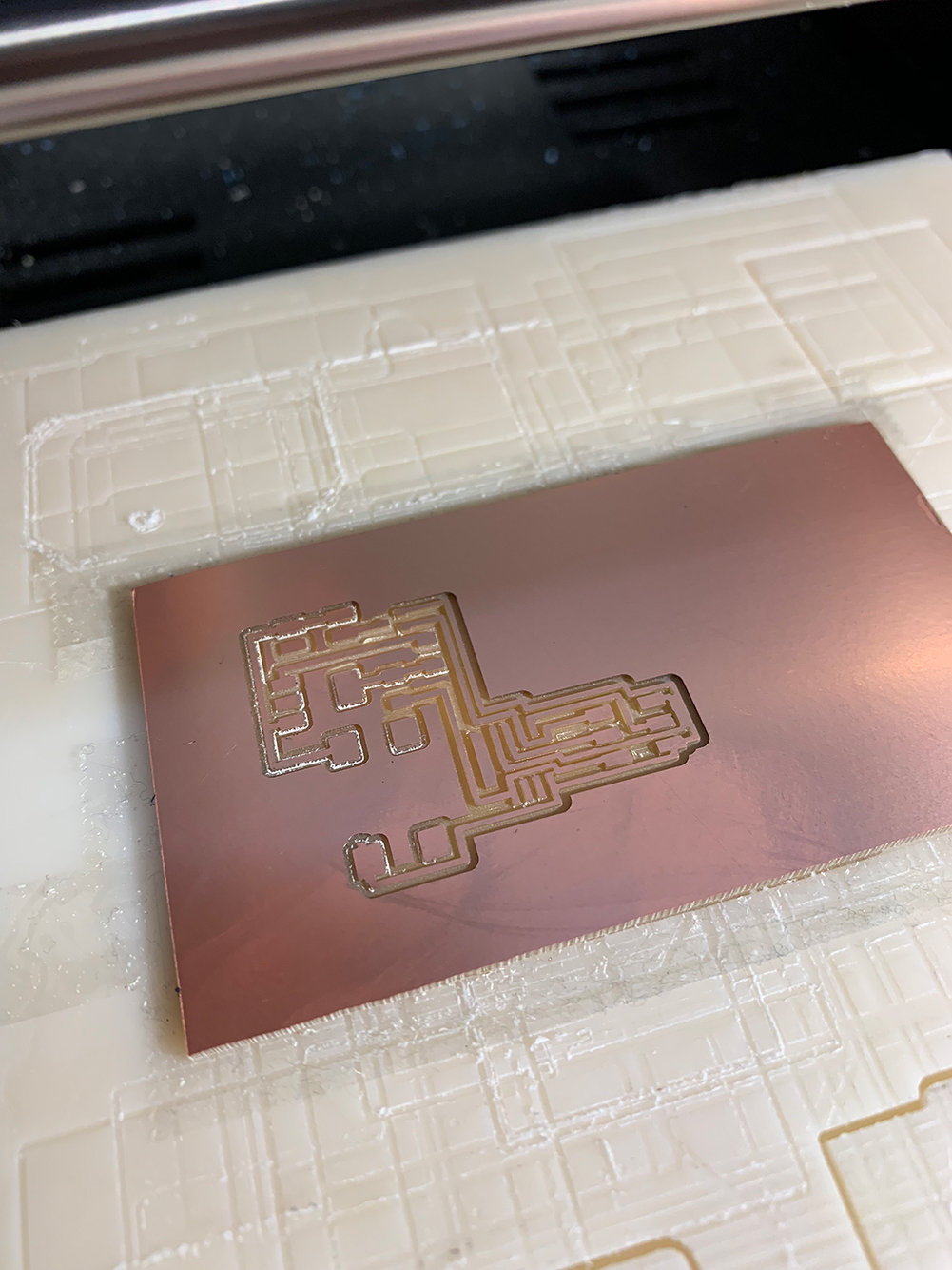
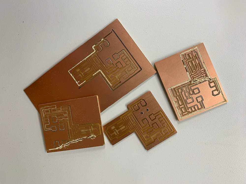
3. I exported the traces and outline and took the files to the SRM-20! I expect the milling process to take about 20 min, but was a downhill slide and eventual loss of a few hours of my life. My outline file was cutting an outer area as well as the desired outline, essentially two outlines. At first, I thought it was a failure on my part, that I hadn’t secured the board well to the SRM-20 bed, but it happened again, so I re-exported the outline file and had to stop it right at the end because it had already cut through on the second path (default settings). Investigating this board revealed two outer routes were too close, so I used that board to practice drilling holes which was seeming less and less possible on the miller with this added outer cut. I went back into Eagle, adjusted the routes, verified my tolerances, remilled and still it started a crazy extra line, which I believe is happening in the export, but TBD on exactly the problem.
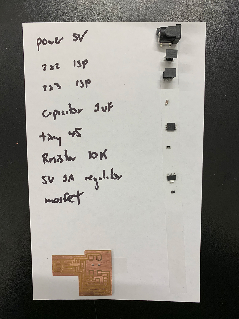
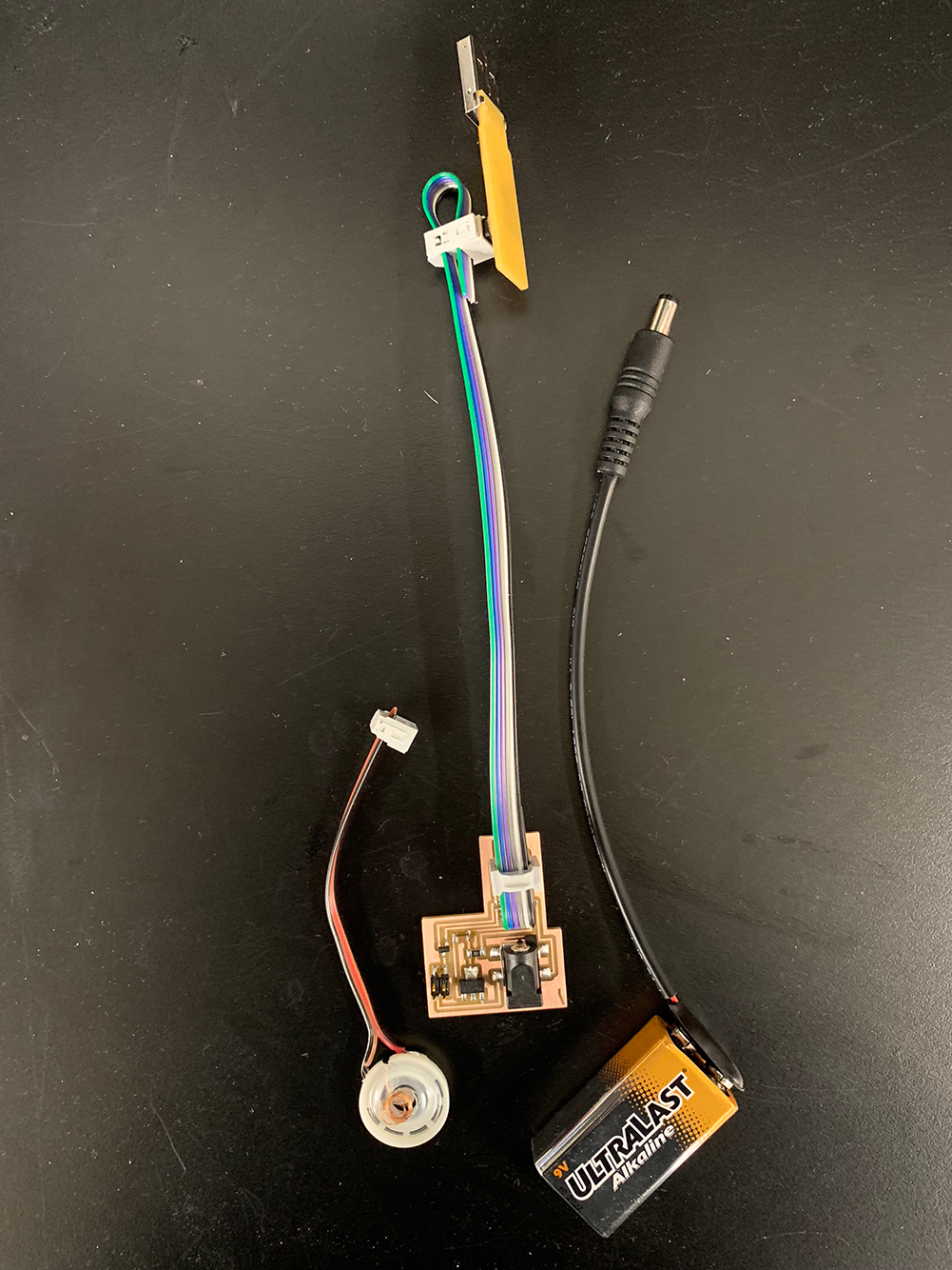
4. I collected all of the required components for the board (8): 5V power connector (1), 2x2 header (1), 2x3 header (1), 1 µF capacitor (1), ATtiny45 (1), 10K Ω resistor (1), 5V 1A regulator (1), and MOSFET (1).
5. I stuffed the board, with the tiniest parts yet and verified the soldering under the microscope. I then tested with the Meterman and it worked perfectly.

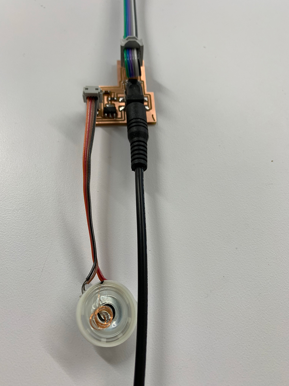
6. I set up a power supply and speaker by first soldering the wires to the speaker. This was extremely difficult as I only have two hands and the soldering points require heating and then holding the leads and then releasing the solder iron while maintaining the angles of the wires until cooled and held in place. As you add more solder for stability the wires want to come up, arghh. I will need to work on alternate methods. I then attached a power source!
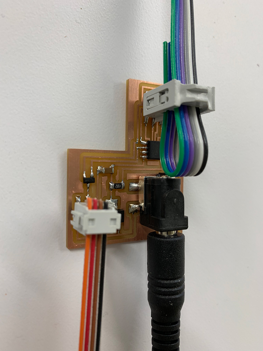
7. At this point I realized I had actually missed connecting my 5V regulator to ground. After my milling debacle I decided to use a small wire connector to complete the circuit. Easy easy, ready to load and test.
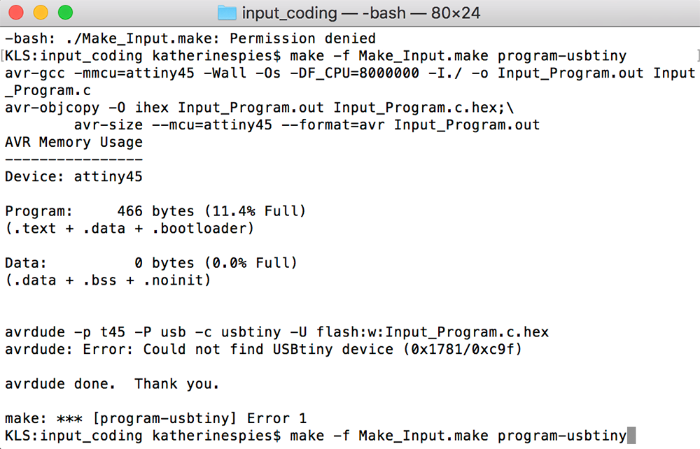
8. Next I modified and loaded Neil’s make and hello.speaker.45.py file and programmed the board via my programmer.
9. Weird frequency outputs!!! What does it mean? How can I modify these sounds?! But they do have a semblance of dinosaur in them…
Struggles
Milling, which was simply an Eagle output issue. And coding… Google, Stackoverflow and Friends are my secret weapon!Tools
EagleIllustrator
MODS
SRM-20
Weller WES51 Soldering Iron
Bausch & Lomb Microscope
Meterman
Programmer Board
CrossPack
HomeBrew
CoolTerm
Splitters/Cables
Friends
Source Files
Link to Eagle SchematicLink to Eagle Board
Link to hellokate.speaker.45.c
Link to Make_Output.make