Assignment
-design a machine that includes mechanism+actuation+automation
-build the mechanical parts and operate it manually
-document the group project and your individual contribution
Goal
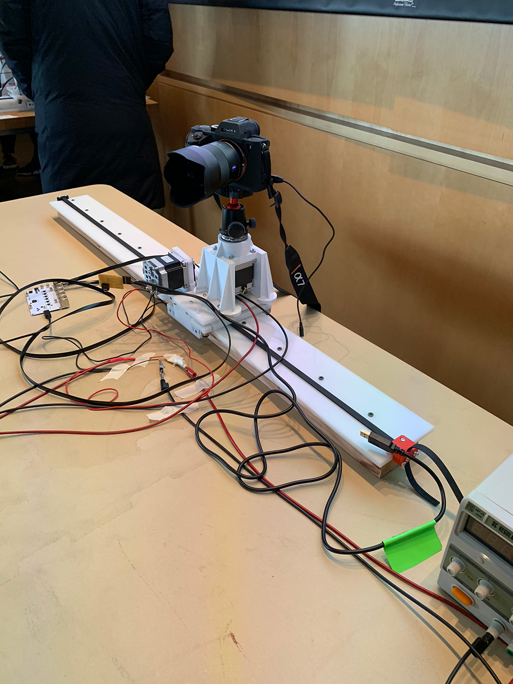
As a team, build a tracked camera rig for creating smooth, panning image sequences and videos.Steps (Team Effort)
Link to Eagle Harvard SiteSteps (Individual Contribution)
I worked on the Assembly Team predominantly focusing on understanding and building Jake’s original design, to include 3D printing and laser cutting components. Here is my write-up:
The Harvard section utilized Jake Read’s kit to begin construction on a machine which could create a 360-degree panorama/timelapse by utilizing three unique axes. To get started we laser cut the components and 3D printed the parts from Jake’s GIT (https://gitlab.cba.mit.edu/jakeread/machineweek-2018). The post-process work to prepare for assembly was relatively extensive. After laser cutting the components in HDPE we had to cut them out from the board and use an exacto knife to trim off the excess material. For the individual holes we utilized a drill press to clear out the individual channels on each of the components. The laser cut could have been slightly stronger, or slower, in order to ensure the pieces were fully cut, to include the holes. After finishing the cuts, as well as the 3D components, an inventory of the supply box was completed.

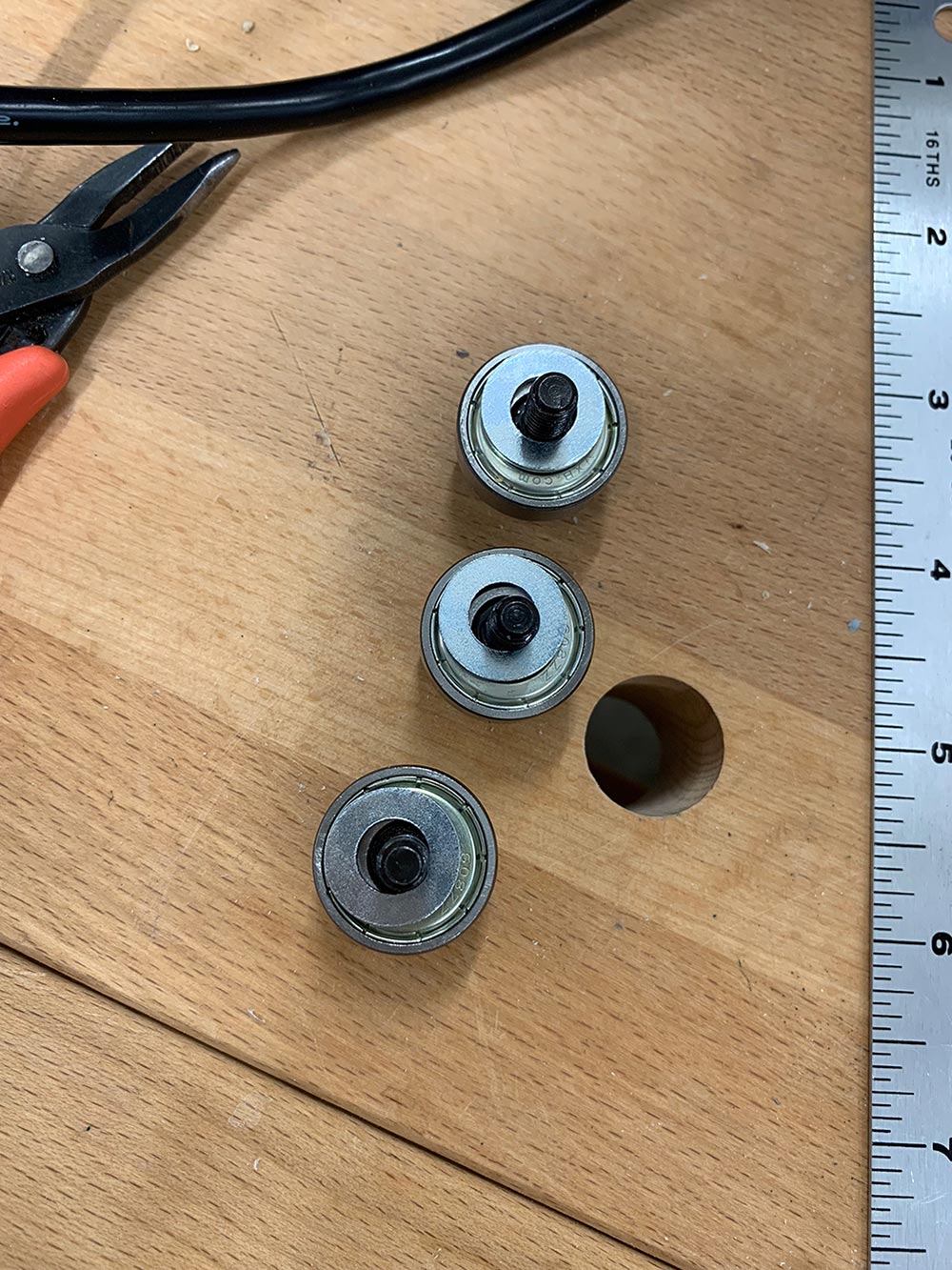
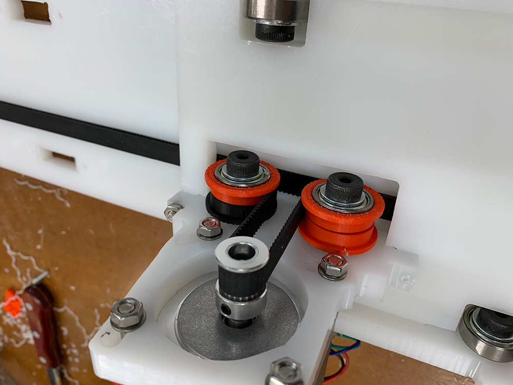
Organization of the components began by utilizing the Assembly sketch. We started by assembling the ‘Preload stacks’, the ‘2x Belt Guide Stack’, the ‘12x Guide Stack’, as well as the hardware and belt components. Ensuring the stacks are accurate is critical for the fit of the gantry to the rail, i.e. the tolerances.
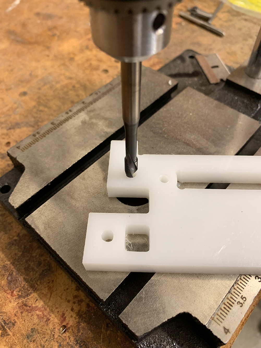
Prior to screwing in the stacks to the HDPE the holes had to be punched for threads. This was simple, but proved difficult in that the HDPE was soft enough that too much stress when screwing the stack into the board easily stripped the punched hole. When this occurred a washer/bolt combo could be utilized, but again, not ideal due to clearances of the gantry and other componentry.
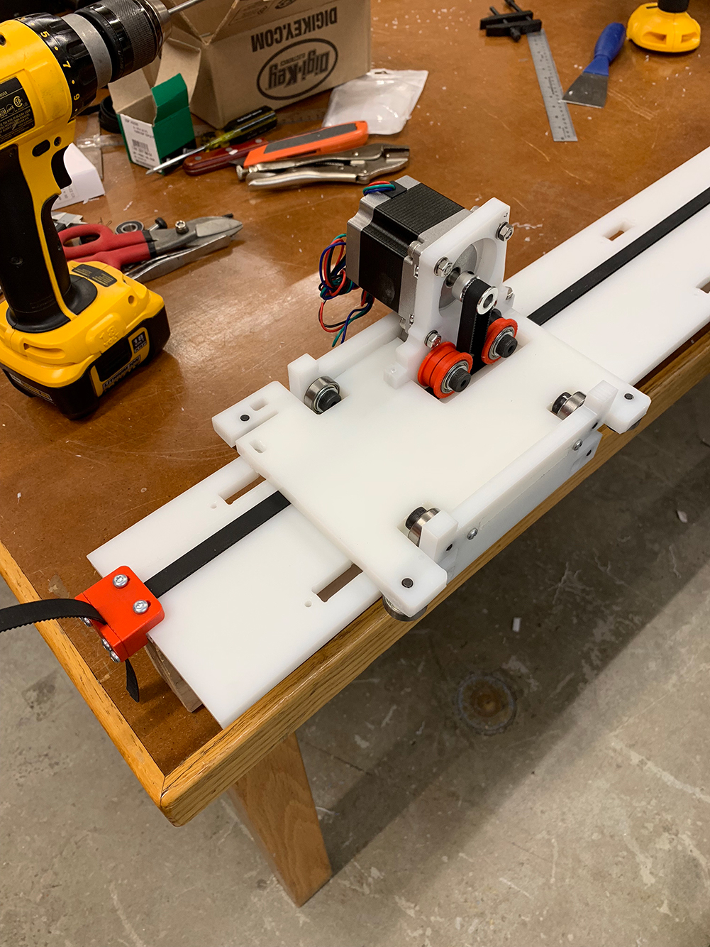
Attention to orientation on the schematic is critical, we initially incorporated the motor and bolts opposite to what was required, which is how we discovered that tapped holes are easily stripped when using HDPE. After attaching the stacks correctly, we began work on the belt.
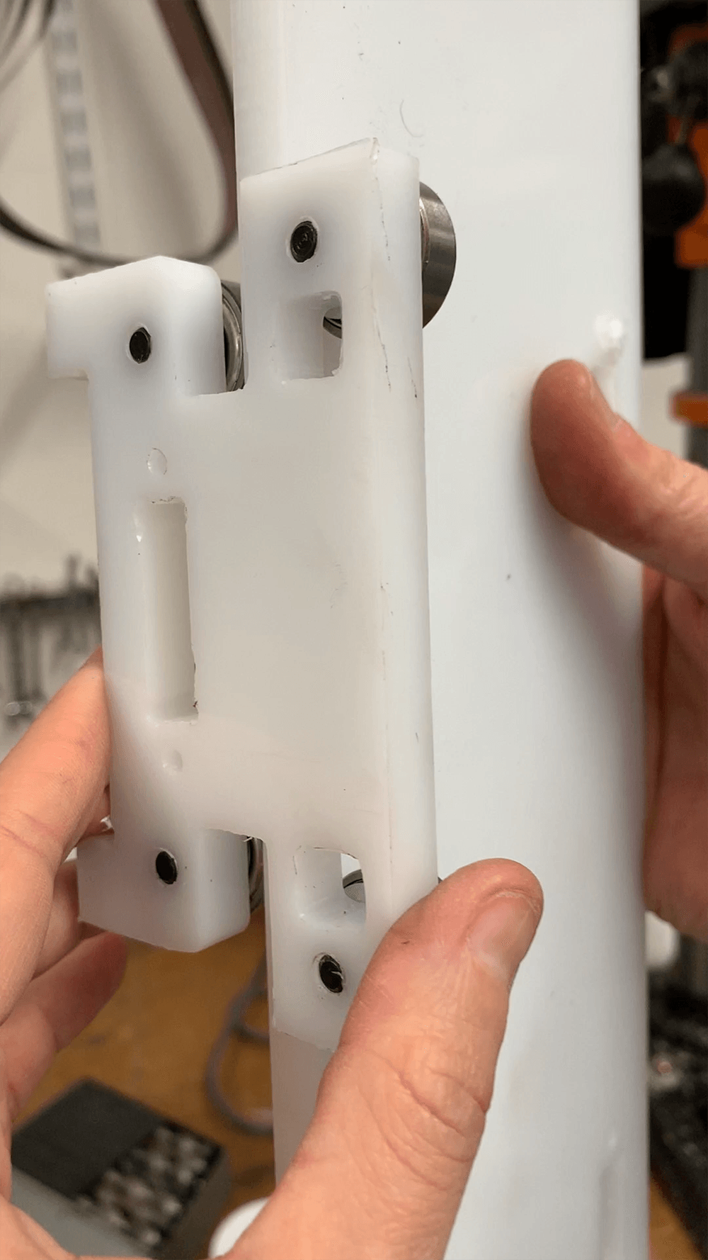
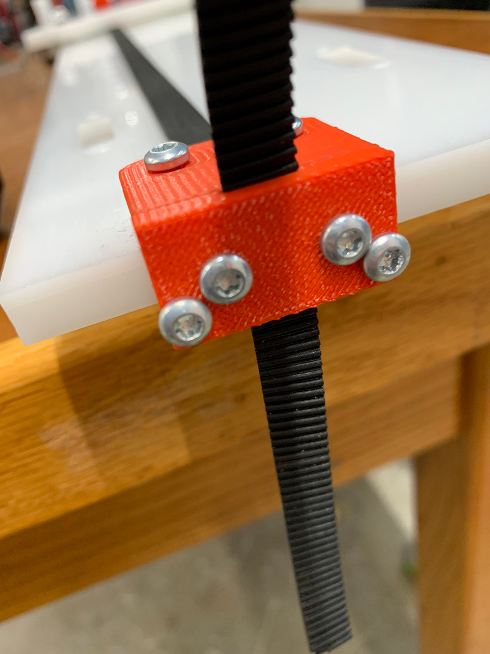
The belt is tricky. The 3D printed pieces require some filing in order to fit the two pieces of the belt through. We started by attaching the simple stacker block and then attached the motor componentry and then worked on the more robust end piece. Sliding the two pieces together, with the teeth aligned, required significant filing of the pieces as well as an attention to detail (and four hands) when sliding and tightening the track through the 3D printed piece. Of note, we are not entirely sure why there are two separate types of connectors for the belt when they both secure the belt in place. Holding the belt tight while then screwing the 3D component to the board is definitely a 2-3 (wo)man operation. It is important to note that prior to tightening the belt down, make sure the belt is thread correctly around the individual guide stacks and motor rotary.

We tested the motor prior to attaching it to the gantry, then established the TinyG four motor board on the machine set-up. We connected the board to power MPJA and the motor to the Motor 1 connection.


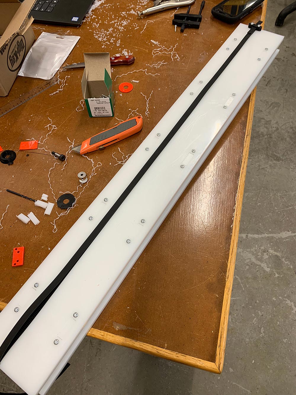
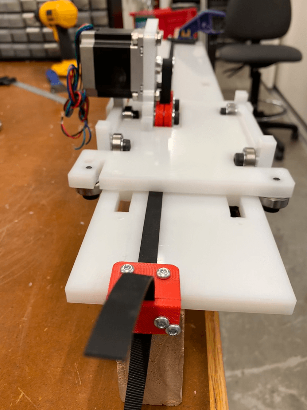
Final assembly was hindered by a fit issue of the gantry to the primary track. The gantry was approximately 5mm too narrow for fitting the track. Options include recutting the pieces or milling out 2.5mm per side of the HDPE. To finalize the set-up we attached the track and gantry to a 2x4 with no problem. The gantry runs very smoothly with minimal friction along the track. The motor requires machining a fit component for the spindle in order to securely have the belt run, which Rob helped us machine.
Lessons Learned:
-Precision matters, Jake’s kit is amazing and the detail in component measurements is quite surreal, that being said, assembly requires precision to ensure the pieces all fit together. The schematic is essential and verifying part nomenclature is essential.-Post-processing is key prior to assembly. Shaving off excess material, drilling out holes, tapping holes, filing 3D components, and more are all necessary for assembly. Measure twice, cut once.
-The belt is finicky and takes patience and four hands. Leave time for this.
-HDPE holes are easily stripped, be prepped to use a washer/bolt to secure components in place.
For the second part of assembly, we were able to utilize the gantry, but recut the track, measured out how to attach the track to a 2”x4” and recleared holes to attach the track to the 2”x4”. Specific attention was paid to clearances with the new set-up, but in the end centering the HDPE track to the 2”x4” was the solution. We ensured there would be clearance of the gantry over the flathead screws attaching the track to the wood base. Additionally, a super long track was desirable, but we simply didn’t have enough of the track rubber to make this happen :( I then passed off the final addition of the track to my teammates!
Struggles
Coordination! Plus of course the typical struggles of making, iterating, and evolving! The key item for initial assembly was just keep going, even with a hurdle, don’t try to go back, just find away around any hiccup, this approach allowed us to assemble a working machine within one day!Tools
Makerbot120W 18”x32” Laser Cutter
Drills
Drill Press
Drill Punch
File
Friends
Source Files
Link to Jake's GIT