Assignment
-characterize the design rules for your PCB production process
-make an in-circuit programmer by milling the PCB, check if you can program it, then optionally try other PCB processes
Goal
Make an in-circuit programmer by milling, assembling, and programming a PCB with a tiny triceratops incorporated into the design.Steps
1. In making my own AVR Programmer I started on Brian’s page and downloaded the Traces (1000 dpi) and Outline Cutout (1000 dpi) files. I modified the Traces file by adding my triceratops outline from the vinly cutting exercise. I tried to balance sizing with the detail of the outline and placement on the PCB, as well as with the bit width.2. I opened mods-programs-open server programs-Roland mill SRM-20 PCB and imported the Traces with Dino file. I adjusted the dpi (a Mac to mods requirement, just double) and set the file mill traces (1/64) and hit calculate.
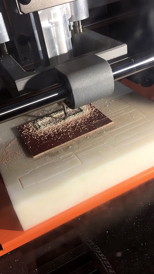
3. Prior to milling, you have to establish the origin. I ensured the 1/64 bit was installed, but tightened high. I used double-sided tape to secure the clean board to the base of the SRM-20. I then adjusted the origin to the lower left corner (as viewed from looking at the machine and from the x/y origin of mods) and lowered the bit to the surface. I calculated again and sent the file.
4. Mill the traces! Once complete I vacuumed out the bed of the SRM-20, loaded the Outline Cutout file into mods in the same way as the traces. Again I had to adjust the dpi, I then set mill outline (1/32) and clicked calculate. I changed out the bit from 1/64 to 1/32 and moved the bit to the origin. I then lowered the bit, recalculated, and sent the Outline Cutout file. Milled board complete, triceratops and all! A small piece of copper had to be removed with an exacto knife.
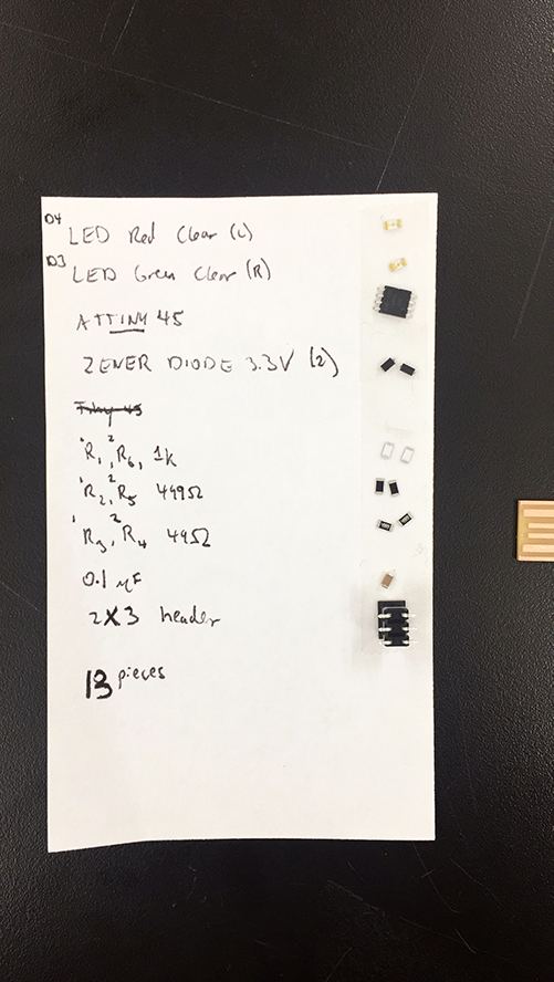
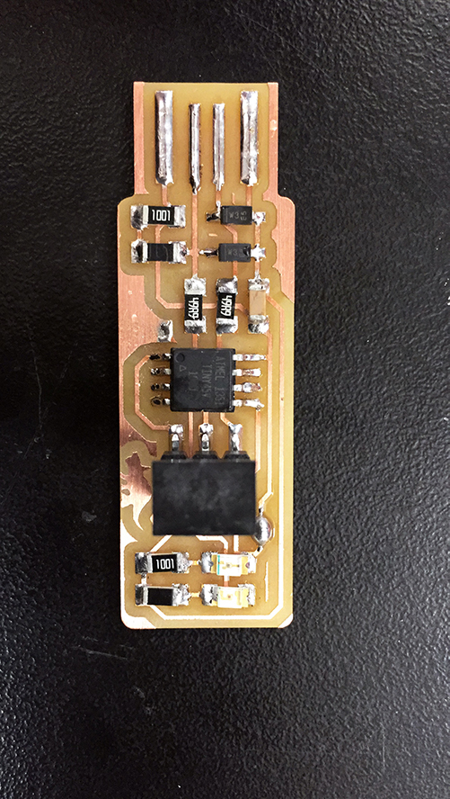
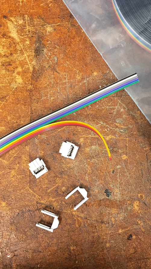
5. I collected the required components (13): LEDs (2), ATtiny45 (1), ZENER diodes 3.3V (2), 1K Ω resistors (2), 499 Ω resistors (2), 49 Ω resistors (2), 0.1 µF capacitor (1), and 2x3 header (1).
6. I turned the soldering iron to 70, ensured the sponge was wet, obtained a role of wire solder, and cleared the workspace. This was a technique building evolution and I found laying a bit of solder on one pad, then reheating and attaching a component the easiest. I also preferred to start with the smallest and highest pieces to ensure I had the room to solder. I continually checked my work on the microscope to ensure a good connection. I also found I could create some flow by how I drew away the solder iron and this allowed me to create a cleaner solder connection.
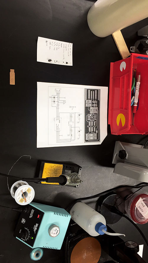
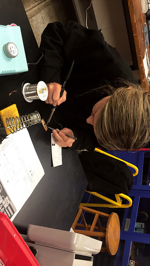
7. After stuffing the board I verified all of the connections under the microscope. I realized I wasn’t qualified to verify anything, so I asked Rob about what I should look for and was able to see what connections were the best and what attributes made for a good connection (i.e. clean solder, full coverage, not too much solder). Then I used the Meterman to test the connections.

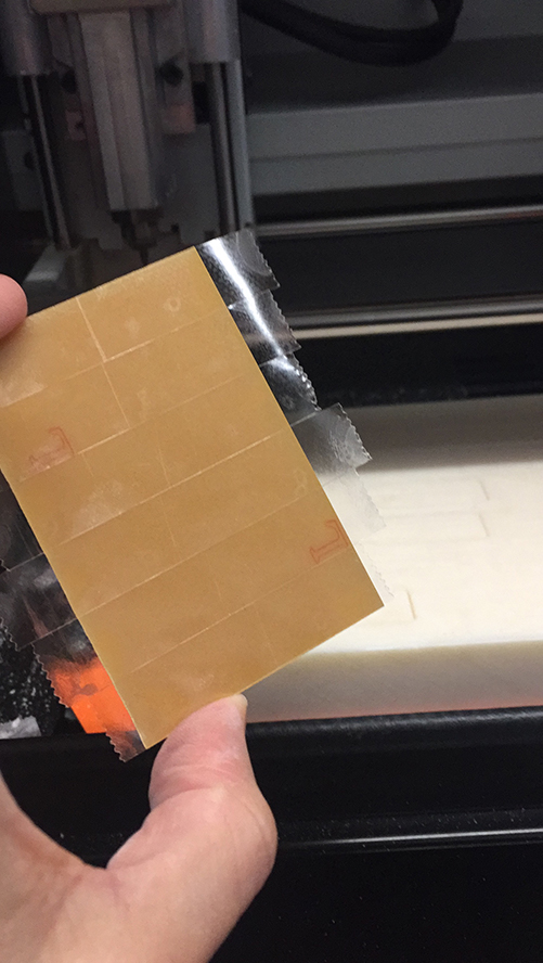
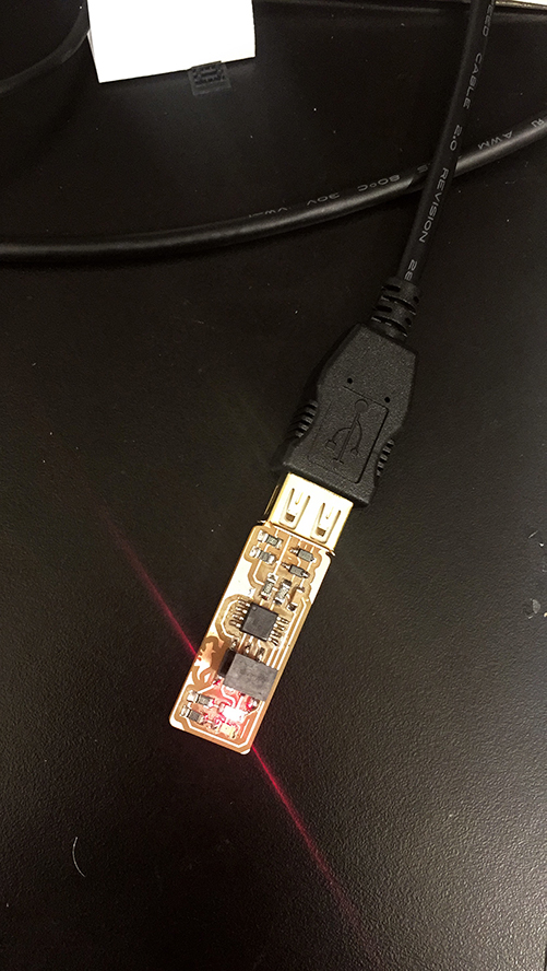
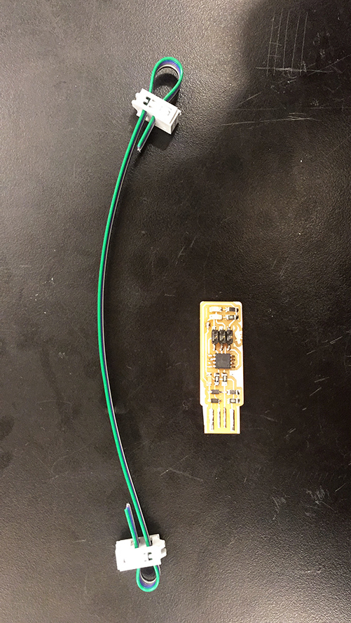
8. In order to use a programming board to program my AVR Programmer Board I added a small paper spring to ensure the pad connections were maintained. My connections were good and boom: power, light, and a programmed board.

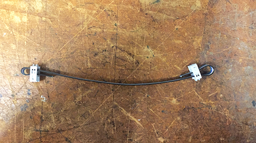
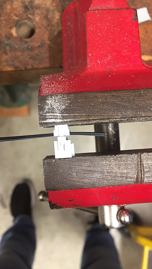
9. Lastly I made a simple connector: clamp, flip, clamp, switch sides, clamp, flip, clamp, complete!

Struggles
The biggest struggle was by far the mental hurdle for an entirely new field. An entire new vocabulary, components, set of tools, etc. Thank you to Brian for making the subject so accessible!Tools
MODSSRM-20
Weller WES51 Soldering Iron
Bausch & Lomb Microscope
Meterman
Source Files
Link to Traces (1000 dpi)
Link to Cutout (1000 dpi)