Assignment
-use the test equipment in your lab to observe the operation of a microcontroller circuit board
-redraw the echo hello-world board, add (at least) a button and LED (with current-limiting resistor), check the design rules, make it, and test it
-extra credit: simulate its operation, render it
Goal
Redraw the hello-world schematic in Eagle, create the Board, mill and assemble the board and program the PCB using the previously made PCB Programmer. Additionally, for the PCB design, incorporate a maze-like board with a plant-eating dinosaur on the hunt for a stash of fruit and vegetables.Steps
1. I attended the electronic design tools recitation and downloaded both Eagle and the Fab Component libraries so I felt prepped leading into this week. To start, I opened Eagle to create a new Schematic file. I utilized the hello.ftdi.44.py board on the website and then added an LED to indicate power to the board, as well as a button and a LED for the button. Finding the right button and the right crystal components within Eagle required a bit of searching, but were available.
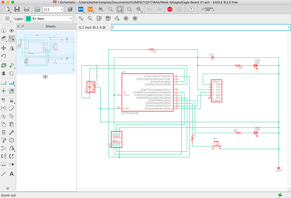
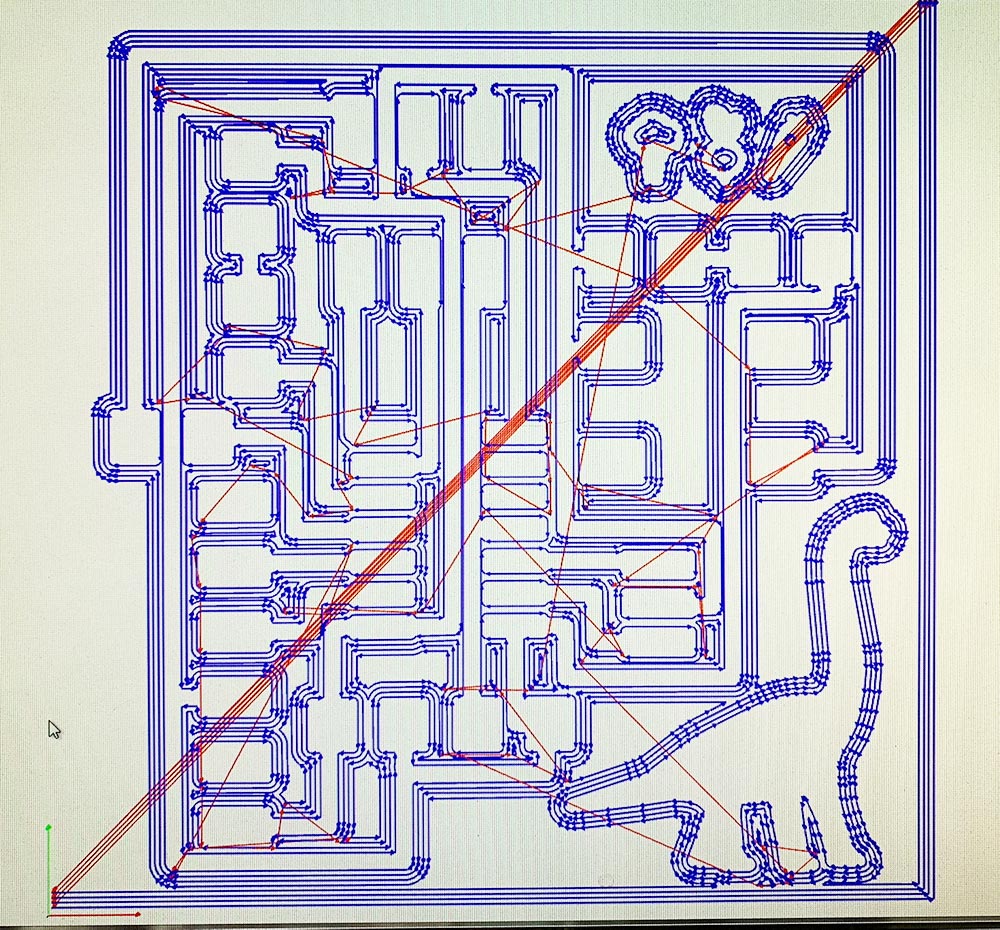
2. After verifying all of the connections, I opened the Board in Eagle and then began placing each of the components. After placing, rotating, and organizing each of the components I tried the auto-route function on Eagle. This gives a good idea of what is required, but then I placed each route by hand. I prefer the 90 deg angles, though it’s purely aesthetic. Understanding the logic is key, but utilizing the Eagle schematic as well as the hello-world example was helpful. I placed the route width at 12 mil and clearance at 18 mil.
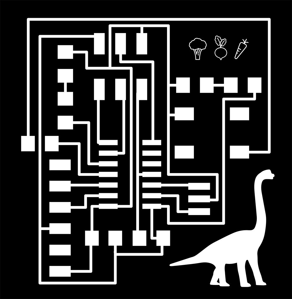
3. I gave the board an outline, verified no errors, and exported as a .png at 1000 dpi. I then imported into Illustrator to add a brachiosaurus as well as a broccoli, beet, and carrot. I then exported as a .png, still at 1000 dpi. I also created an outline file for the milling process in Illustrator.
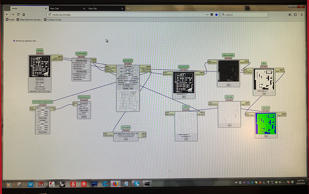
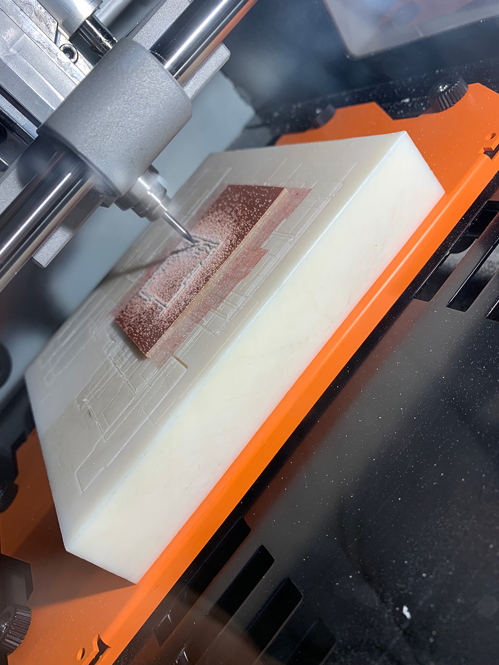
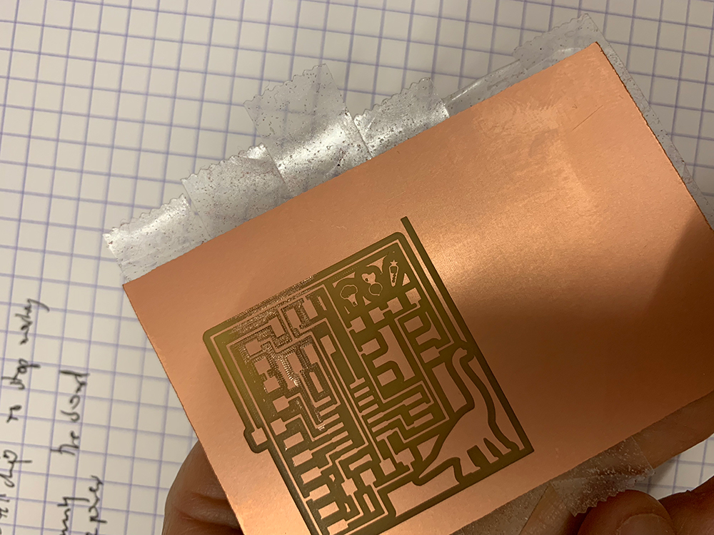
4. Milling on the SRM-20, basically becoming a pro. I loaded the initial trace file, set the dpi to 2000 (Mac to mods), and set the mill traces (1/64) at the reference settings with offset at 4. After calculating the mods file, I moved the SRM-20 to the origin, verified the 1/64 bit, dropped it to the board, and then sent the file to mill. The mods file added an extra set of trace lines along the bottom as well as the right side of the .png. My first mill left some copper in the bit path and the machine froze and prevented me from resending the file at a deeper cut depth. This is where I had to reload/on/off/reset/Rob/cry in order to get the file to load again, obviously not a pro. I then increased the cut depth to 0.005 in from 0.004 in. After milling, I used a small piece of scotch guard to eliminate any surface burrs. I then investigated the board under the microscope to ensure free of burrs and fingerprints.

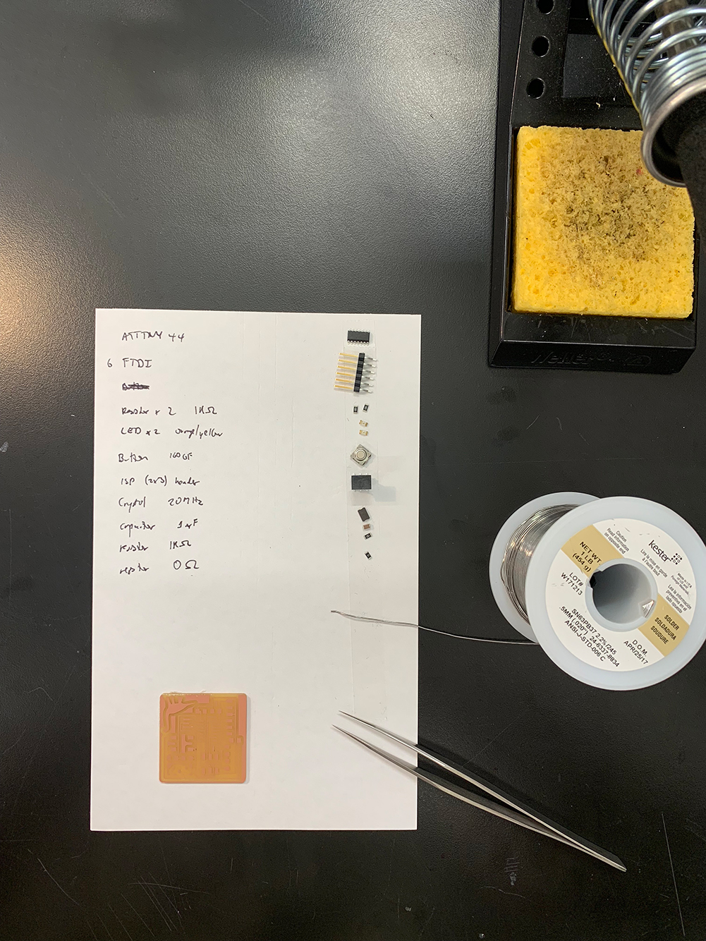
5. I first collected all of the required components for the board. (12): ATtiny44 (1), 1K Ω resistors (3), 6 prong FTDI (1), LEDs (2), Button, 2x3 header (1), 20 MHz crystal (1), 1 µF capacitor (1), and 0 Ω resistors (1). I initially chose the wrong crystal, but figured out it was wrong because the piece only had two contacts and my piece needed two contacts and a ground.
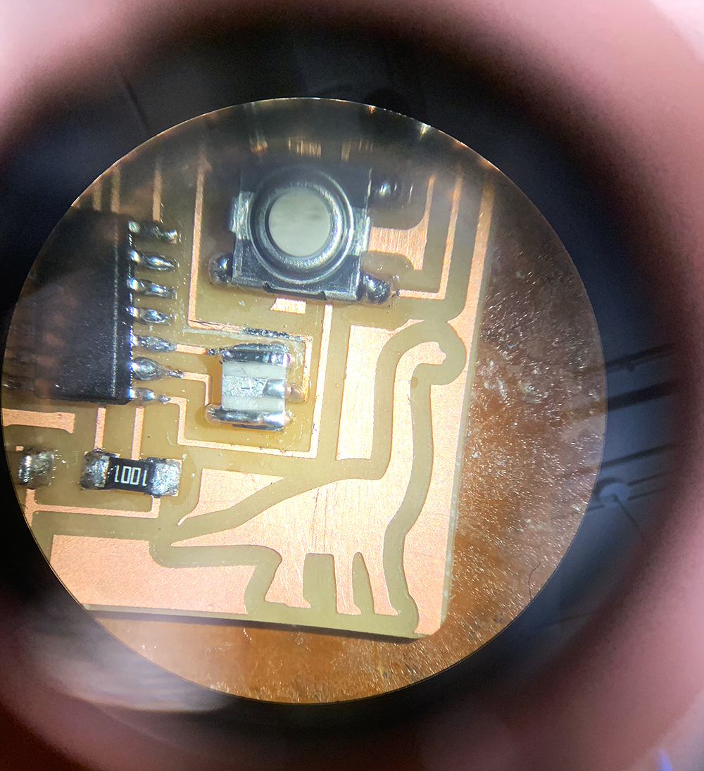
6. Solder, solder, solder. The hardest component by far was the CER Resonator. I initially tried to solder it like a resistor by adding a bit of solder to the board, reheating, attaching one side, and then completing the other side. But I was worried about the center connection. I then disconnected the component, added solder to each pad and then tried to reattach. At one point the copper was starting to come up, so I heated up one side, pushed down, added solder, and then committed to not moving the component anymore. In the end I did not need to flow solder under the component to the ground, I just need to place the piece and solder the edges.
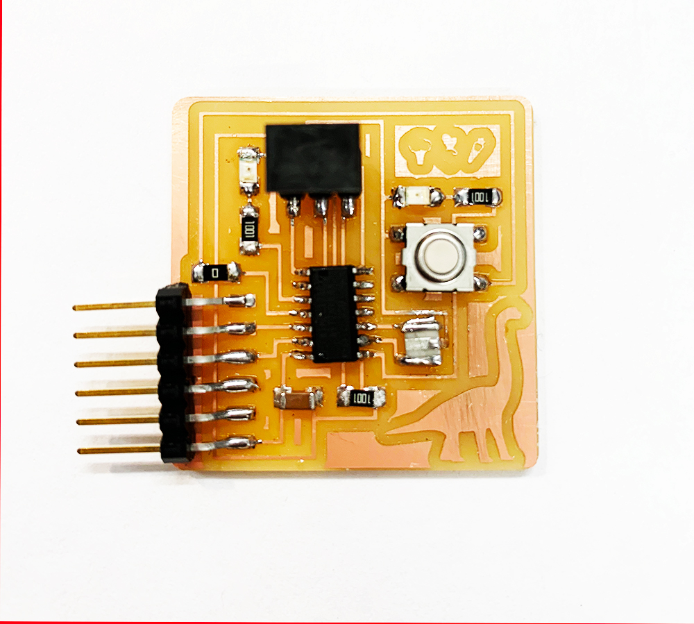
7. Looked at the board in the microscope to investigate the soldered joints. Looks good! Had Rob have a look and he gave me a few pointers on improving my soldering connections, specifically, heating to create flow and then pulling down towards the copper connection. Also, just ensuring enough solder!
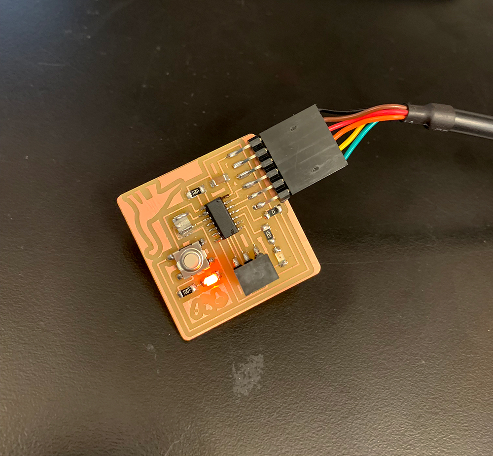
8. I connected the board to power, and the LED light came on! Awesome!
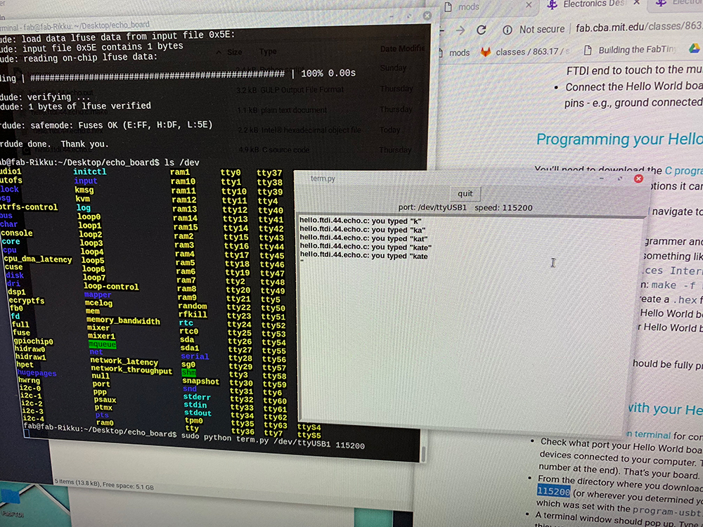
9. I then used the echo hello-world program on the shop computer to load the board, success!! I got a read back of K, then A, then T, then E!
Struggles
Finding the components in Eagle were tough, but using the *item* search function made it easier. Connecting the schematic is easy, but when you go to the board routing the connections is a true art form. I got down to one button connector with no way to connect to a pin on the ATtiny44, so I disconnected and moved all of the pieces around. The board got crazy, so I went back to the first design, added a 0 ohm resistor for a jump and I was set. I also struggled milling on the SRM-20, which had some loading issues that eventually reset with some on/off/restart/reloads.Tools
EagleIllustrator
MODS
SRM-20
Weller WES51 Soldering Iron
Bausch & Lomb Microscope
Source Files
Link to Eagle SchematicLink to Eagle Board