Assignment
-measure something: add a sensor to a microcontroller board that you have designed and read it
-probe an input device's analog levels and digital signals
Goal
Sense the presence of an IR light with the potential to identify unique IR lighting patterns.Steps
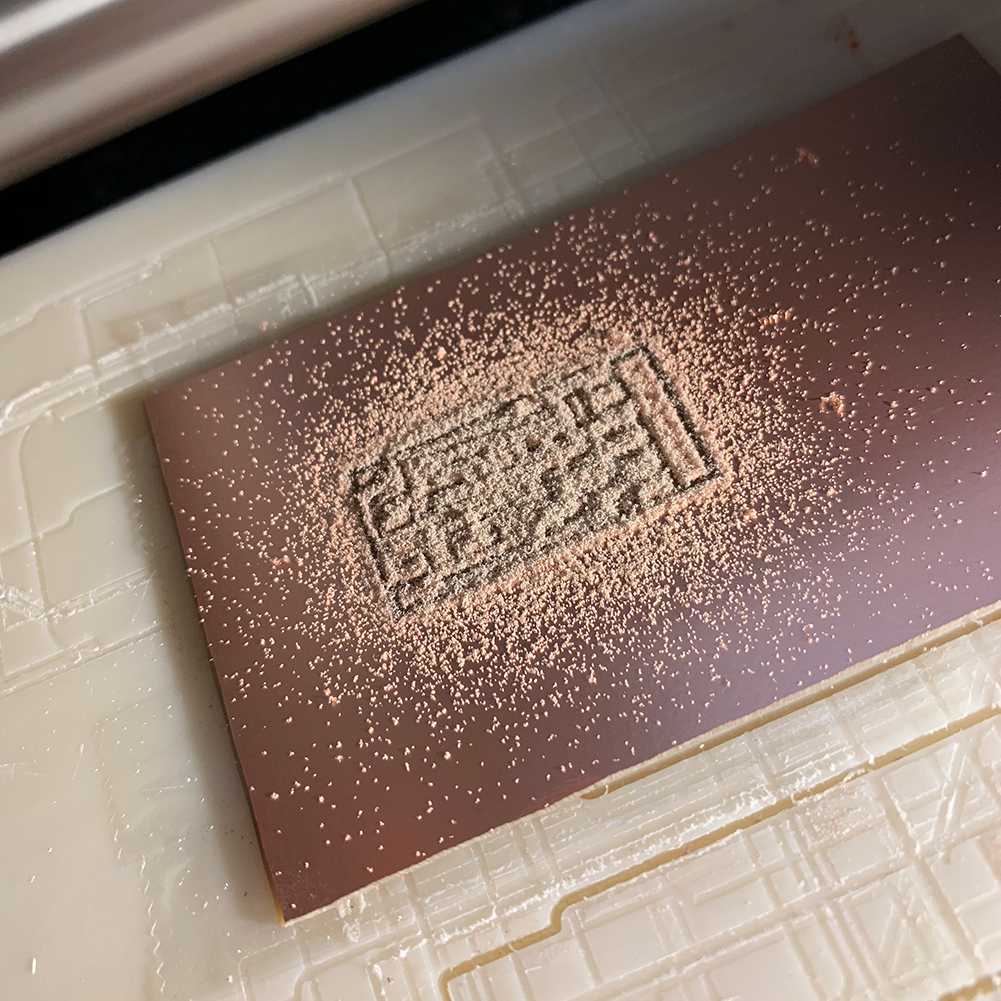
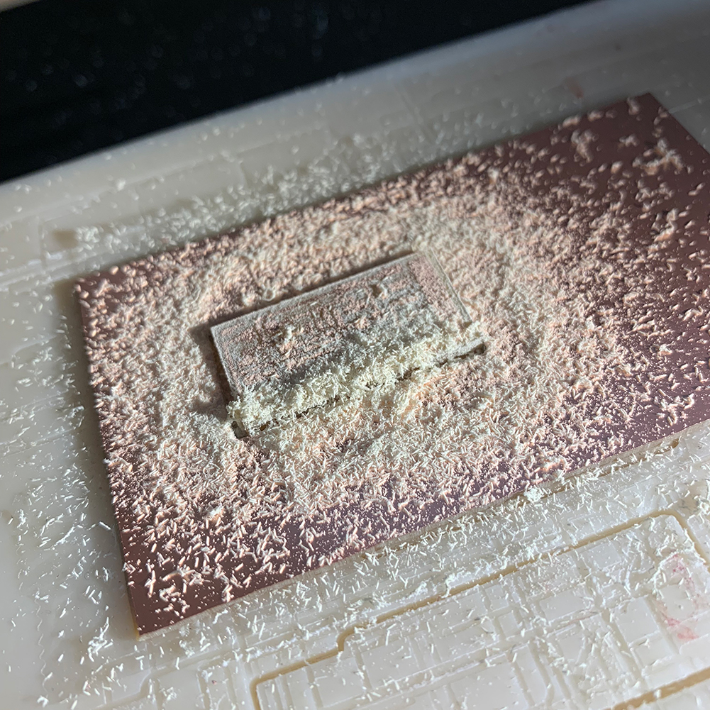
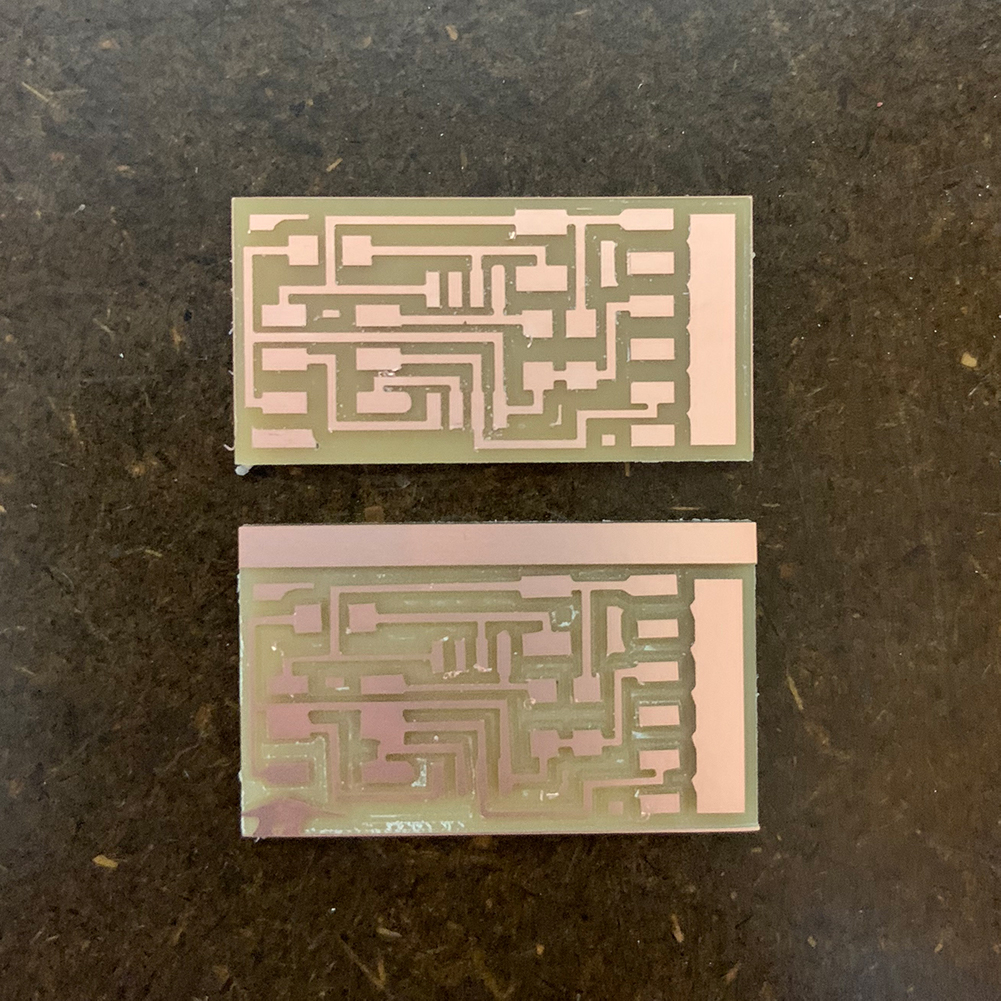
1. Make a new board! I leveraged the hello.light.45 board to start and modified it to include an LED to indicate power as well as a signature dino, this iteration had an anklyosaurus. I had a large number of PCB milling failures and went back to the simple board, without the dinosaur. I believe I was having issues with the transition from Illustrator, after adding the dinosaur silhouette, to mods for milling. I have used this method three times before, so still unsure about the exact problem. Milling on the SRM-20 was otherwise the same as always. I loaded the initial trace file, set the dpi to 2000 (Mac to mods), and set the mill traces (1/64) at the reference settings with offset at 4. After calculating the mods file, I moved the SRM-20 to the origin, verified the 1/64 bit, dropped it to the board, and then sent the file to mill. I then repeated with mill outline and 1/32 bit and did some post-processing to remove surface burrs.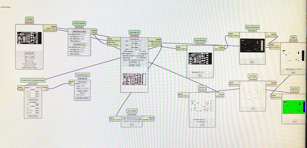
2. I first collected all of the required components for the board (8): 2x2 header (1), 10K Ω resistors (3), 6 prong FTDI (1), ATtiny45 (1), 1 µF capacitor (1), and IR phototransistor (1). I assembled the board after consulting the AVR guide for the IR light detector, aka phototransistor.
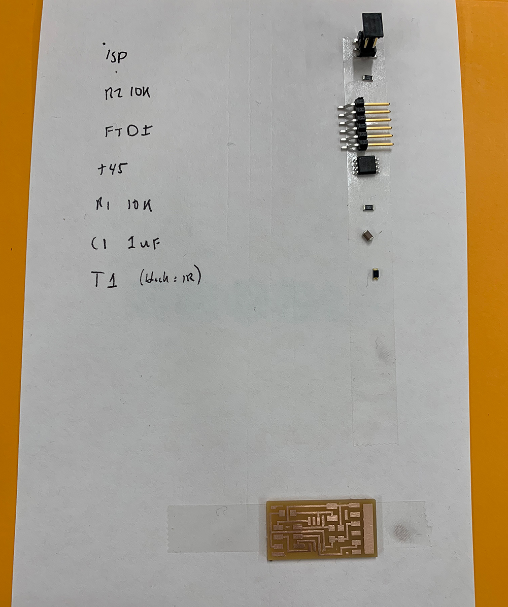
3. I then observed the board under the microscope, added solder as necessary and then used the Meterman to test each of the connections input and output. No problems! Feeling like a pro, or at least not a total rookie.
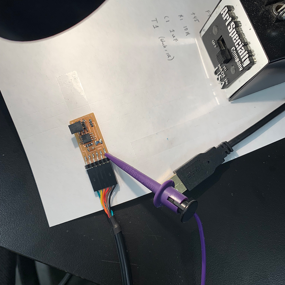
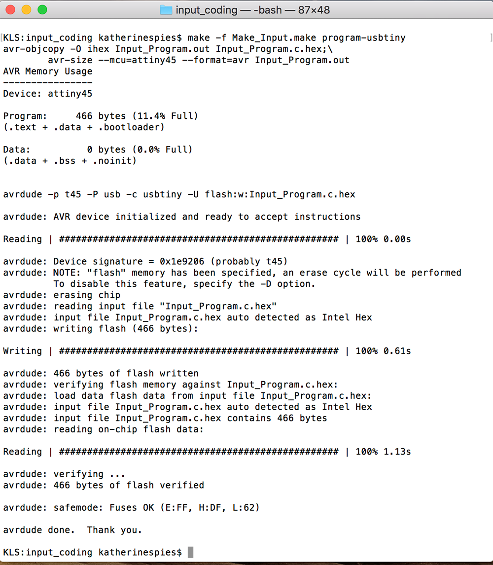
4. Next was making the Make and Program file for the Input board. I leveraged Rob's Make and Input Program to get started. With my board I had to adjust the MUX code for PB3 as well as change program names etc. I used my programmer, plus a USB step down, plus a FTDI connector in order to have my computer 'see' the board and then be able to write both the Make.make and the Input_Program.c. Initially avrdude did not load the Input_Program. I double checked all connections, tried to load on a known working board (which worked) and then just tried again. Annnnd, it worked!
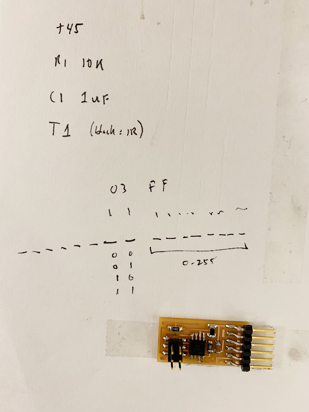
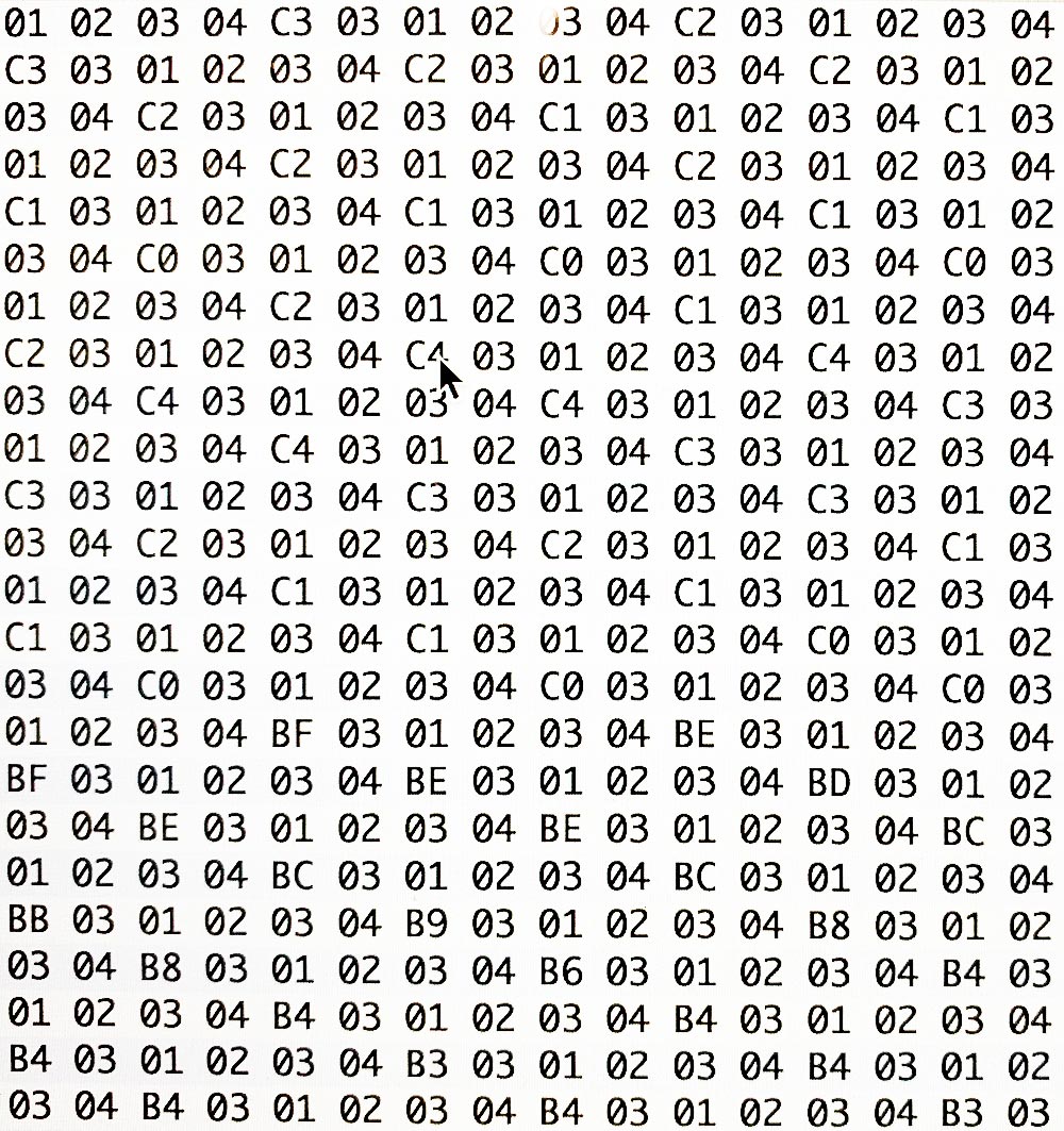
5. I then tested the board with and without light and could see the change in voltage on the Meterman, essentially a binary test of the IR phototransistor. I then downloaded CoolTerm and connected the board in order to read the hex output. I was able to see both 'high' and 'low' with the hex!
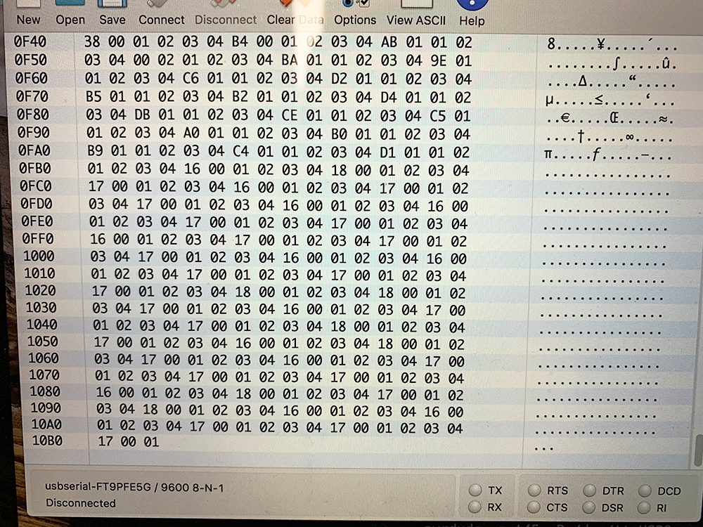

6. I started working on converting the hex to indicate light versus dark, but that is still in work!!
Struggles
Understanding the hex is a work in progress and will require spending more time with the output. Also, only every label a make file make!Tools
EagleIllustrator
MODS
SRM-20
Weller WES51 Soldering Iron
Bausch & Lomb Microscope
Meterman
Programmer Board
CrossPack
HomeBrew
CoolTerm
Splitters/Cables
Friends
Source Files
Link to Eagle SchematicLink to Eagle Board
Link to Input_Program.c
Link to Make_Input.make