Team: me, Jasmine Schlichting, and Victoria Shen
With help from: David Selles, Lins Derry, Jeffrey Wang
and Abdul Jamjoom
Camera goals for the 360-degree panorama/timelapse machine
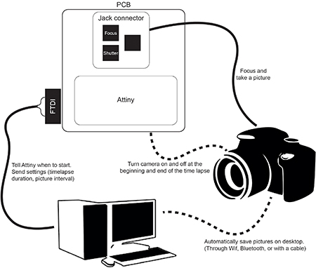
The user adjusts the desired settings (video versus picture sequence, timelapse duration, shutter speed, brightness etc...) in the code, from where on the machine takes care of the rest (turning the camera on and off and taking pictures).
Turn the camera on an off using code, rather than using the button on the camera to manually turn the camera on and off. Use code to have the machine automatically focus and release the shutter. Automatically save the pictures in the same folder on the computer, thereby eliminating the need to transfer the images from the camera manually.
Helpful websites to get started
EOS Utility: a free software application that can control Canon cameras when tethered to a computer.
Arduino to take a picture every x seconds for y minutes. For our machine application we would not need the buttons to change the settings. Instead, the user would alter the settings in the software.
Examples integrating Arduino and a shutter release cable: here and here.
The use of a jack connector to control the camera's shutter and focus.
Using an eyefi SD card to wirelessly, automatically, and in real-time transfer the pictures from the camera to the computer.
Build your own camera using TTL Serial camera: TTL serial camera, WiFi Arcuino-cam, OV7670 camera module with Arduino and VC0706 camera module with Arduino.
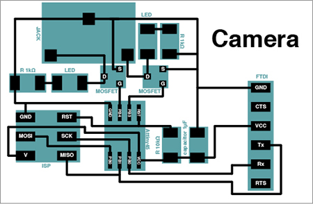
Jack connector and board design
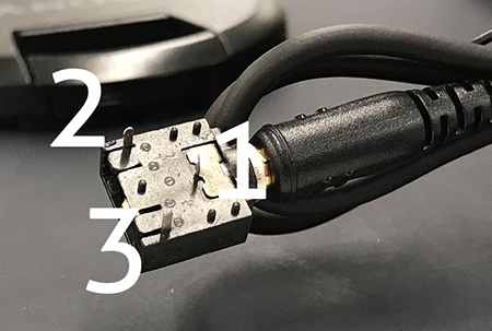
The focus and shutter triggers can be controlled "outside of the camera" using a cable and a jack connector. David and Lins figured out how to use a jack connector (see picture and video). A 3.5 mm female jack has thee pads, numbered 1, 2, and 3, in the pciture. A connection between pad 1 and pad 2 will focus the camera. A connection between pad 1 and pad 2 AND pad 1 and pad 3 will trigger the shutter (e.g. take a picture). Good practice is to first focus the camera and then take a picture.
To control these connections we designed a PCB board including an Attiny45, mosfets to regulate the connection between the pads on the jack, and an FTDI connection to both send and receive information. The board needs to receive information on the timelapse duration and picture interval set by the user of the machine and will send out information regarding the status of the camera (e.g. if the timelapse has started, finished, the number of the latest picture it has taken etc...)
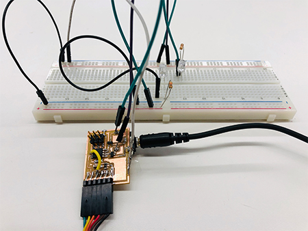
In the process we adjusted mistakes in the board design and added LEDs to test the performance of the mosfets.
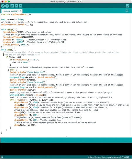
Programming
The main issues we experienced during the programming of our board were space issues (the sketch often used too much program space and global variables used too much of the dynamic memory, preventing us from uploading the sketch) and getting the serial to work in the way we wanted to communicate with it (entering a sequence of values and storing those values for the code to use). Jeffrey and Abdul came to the rescue and helped me and Jasmine to get the Serial to perform in the way we wanted it to and reduce space. To solve the space issue, we avoided using Serial.readString() and print statements are short and sparse (e.g. "Init", "D", "I", etc..)
To get the shutter (pin 3 on the jack connector) to work properly, by trial and error Jasmine found out we had to activate the mosfet for the shutter first in order to achieve the voltage drop necessary.
The
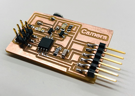
New board
After verification that the board worked seamlessly with the code, I made a new board to fix earlier mistakes and added LEDs for visual indications on the performance of the mosfets.
Starting the picture sequence:
When a connection has been established, "Init" will be displayed in the serial monitor. Typing an "s" starts the process of inserting parameters. The monitor displays a D, prompting the user to type a timelapse duration (in seconds). The duration should be entered in the following format: a round number ended by "s" (e.g. 2400s). Subsequently, the monitor displays an I, prompting the user to type an interval duration (in seconds), which should be entered in the same format as the duration. Once entered, the camera will directly start the timelapse process and take pictures for the specified duration and with the specified intervals.