Final Project Haptic Heart
how to make (almost) anything
Final Project
Idea 0: Data Visualization Art Experiment
In the coming weeks, I will be rigorously working towards a final project that integrates all the knowledge I’ve gained this semester at MIT and Harvard. Here is the global perspective on my vision and strategic approach to realizing it…
For my final project in How to Make (almost) Anything with Neil Gershenfeld, I will design and fabricate a costume with programmable LED’s reflective of Instagram hearts as well as the void of them. For my final project in the Art, Design, and the Public Domain (ADPD)Proseminar with Krzysztof Wodiczko, I will use the costume as a techno-cultural prothetic in a performance. Conceptually, I intend to research the publicness and performativity of images, the intimate space between viewer and image, and how the private spheres of both authors and viewers have led to a public sphere in virtual space. While the costume is embedded with lights that serve as an accessible metaphor for visibility and even monumentality on social media, I am equally interested in using the dark as a metaphor for the more ambiguous aspects of Instagram.
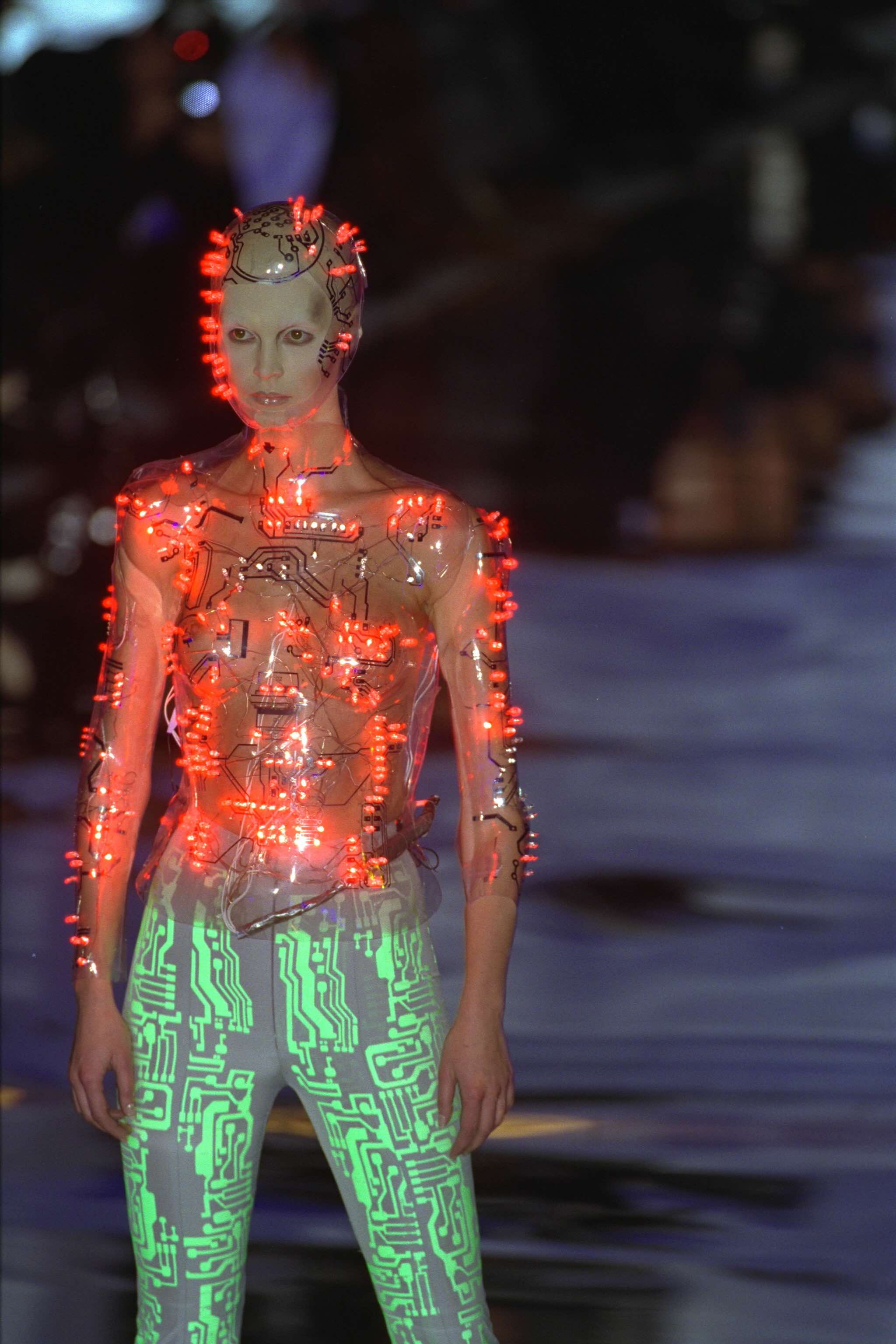
For the costume design, I draw immense inspiration from Alexander McQueen’s 1999 fall/winter collection for Givenchy. With Neil and Krzysztof’s encouragement to replicate designs we admire, with proper acknowledgement of course, in order to learn from them and to discover our own process along the way, I will attempt to revive the below bodice.

Further, I will bring movement to the bodice via contemporary dance choreography. The below highlights the movement vocabulary I will develop towards this end. Regarding my choreographic intention, I am researching how creating in the private sphere (in this example, my bedroom) for a virtual audience (Instagram) affects my gestural choices. At a meta level, I am eager to see how the choreography will resonate in December in view of a live audience.
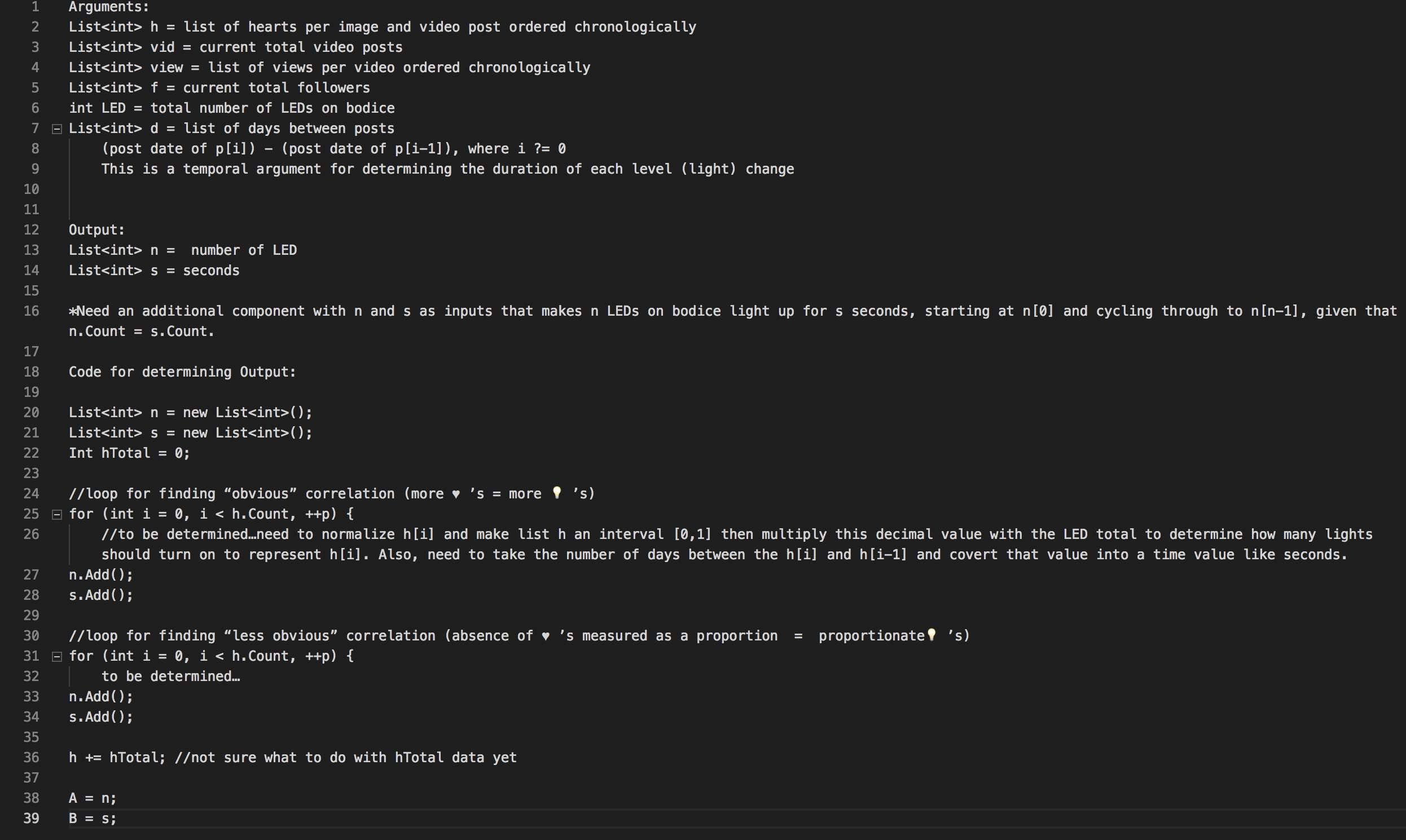
At the programming level, I have several ideas shown partially in pseudo code below. Simply expressed, the LEDs will be “played” like a symphony, with temporal lighting changes being commensurate with my Instagram data. Combined with the conceptual elements researched choreographically, the performance will be a data visualization art experiment.
Final Project
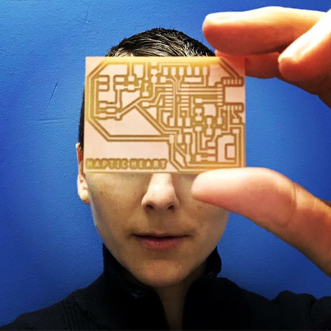
Idea 1: Performative Body, Haptic Heart
After looking more closely at the final project guidelines, I realized my Data Visualization Art Experiment may not check off enough of the boxes which cover “2D and 3D design, additive and subtractive fabrication processes, electronics design and production, microcontroller interfacing and programming, system integration and packaging”. If I pivot with my haptic heart idea, I can incorporate more of these requirements into my final project.
My vision for Performative Body, Haptic Heart, is to wear a heart rate sensor that wirelessly sends a signal to a vibration motor in the silicone heart so that as I dance, the viewer holding the heart can feel my heart beat. The goal is to amplify the kinetic qualities of dance for audience members who typically must depend solely on their visual and auditory apparatuses to experience a dance performance. In the longterm, I imagine how a symphony of haptic feedback actuators could be coordinated to give an audience a surreal somatic experience while watching not only dance, but sports as well. In particular, I am inspired by the Music:Not Impossible project where a “wearables set [that] includes a harness, two wristbands, and two ankle bands, supplying 8 distinctive areas of vibration across the user’s body” generates a ‘surround sound’ musical experience for deaf people.
http://musicnotimpossible.com
Searching for past projects on the How to Make (almost) Anything database, I came across Oscar Rosello’s final project that also incorporated a heart rate sensor, vibration motor, and modeled heart for the purpose of enhancing mediation. Referencing his materials has been a mega help!
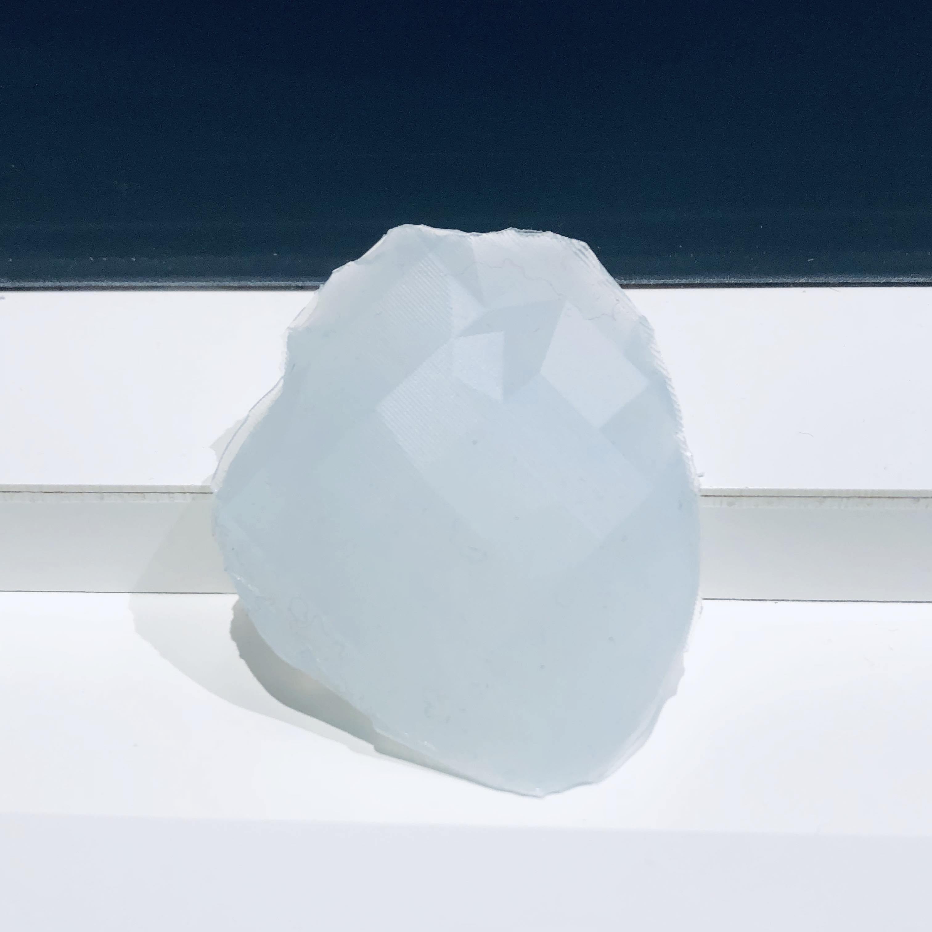
Here is a recap of Week 08: Casting and Molding where I prototyped a silicone heart…
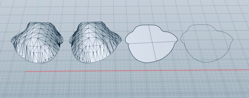
The CAD process for designing a heart took three work sessions with each session approaching the design solution very differently.Session I: My initial approach was to import a 3D model of a heart from the web. While I found a stunning model, the entire design was a single mesh making not only editing but conversion into a solid model tedious. The first step I took was to use a cutting plane to trim the protruding veins and capillaries. Not very dexterous in Rhino, the best I could do was, more or less, to shave off the top. Next, I attempted to make a mesh sphere to fill in the hole, blending the seams using the control points. Unfortunately, when I followed the mesh-to-nurbs command, my object was unable to convert into a solid which affected my ability to use the boolean-difference command successfully.
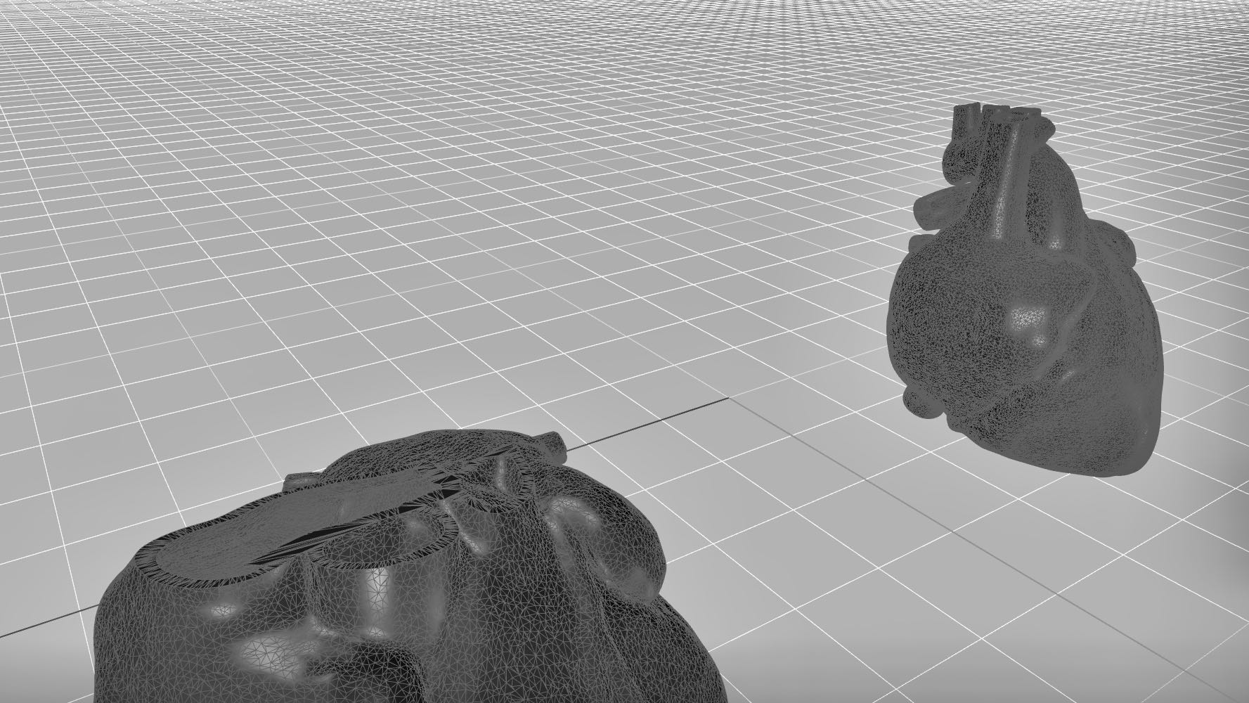
Session II: My second attempt at modeling a heart began with my dropping a photo of another 3D model into my Rhino interface. I then worked in 2D in the top view and traced the outline of the heart using the interpolated curve tool. This worked well! I made two traces, one of the front side and one of the back side. Next, I stacked the traces in the perspective view and then created surfaces all around. But since the shape looked so flat and angular, I decided to abandon it.
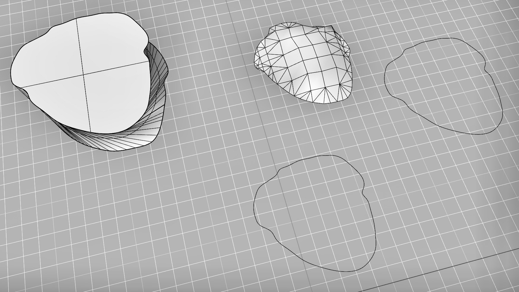
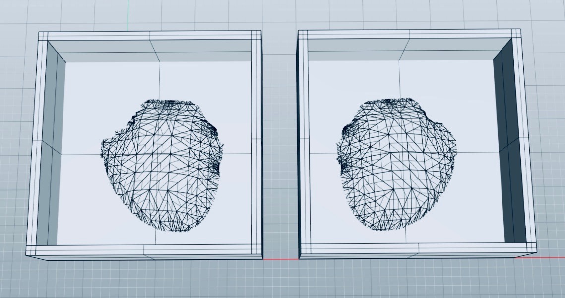
Session III: I returned to the 2D traces but with a new idea: to create from them a mesh surface that could be manipulated into a 3D shape using the control points. I did this per heart half, after which, I capped the mesh surface from below. The two shapes converted beautifully into solids allowing me to create my two molding blocks no problem.
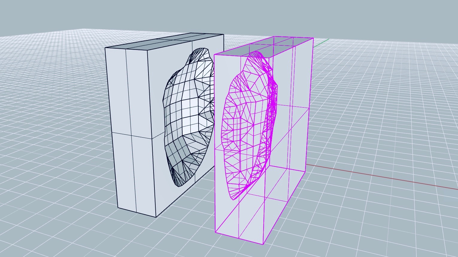
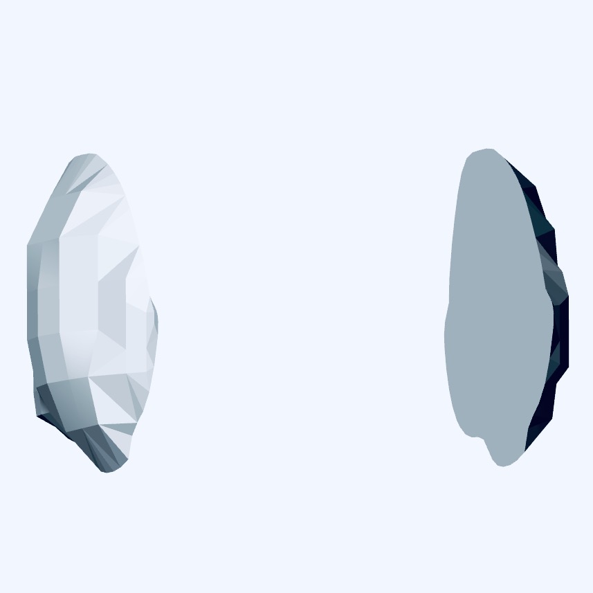
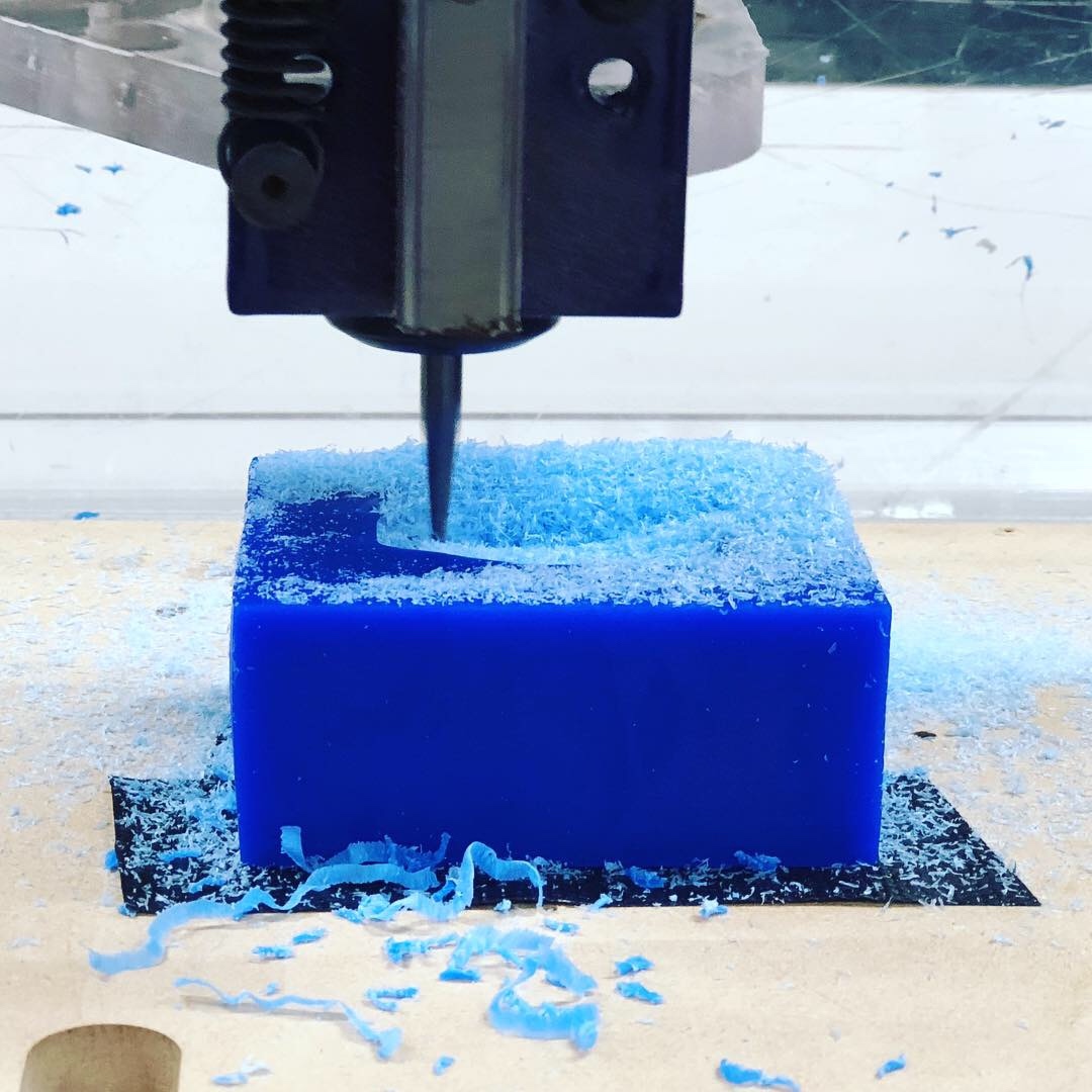
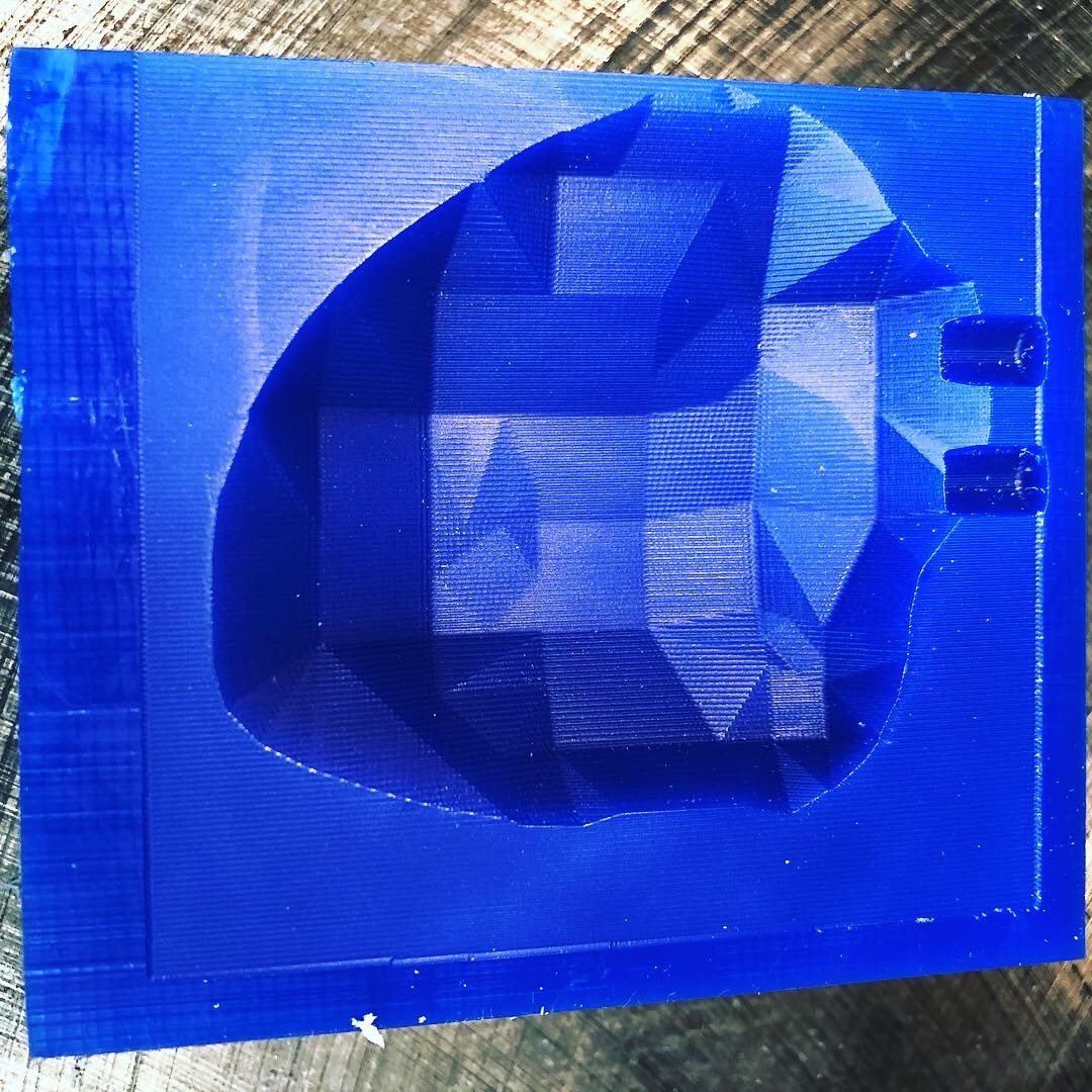
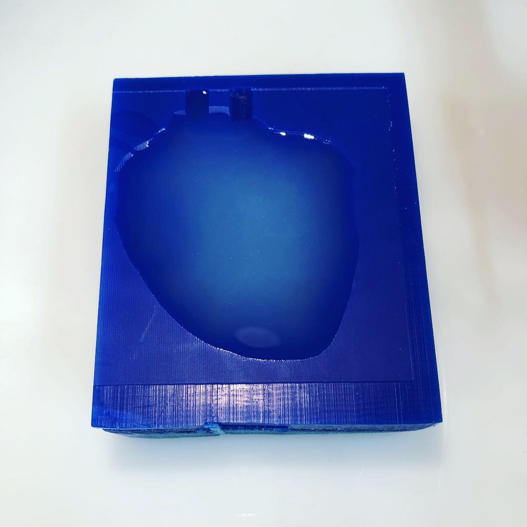
On the ShopBot, I used V-Carve to import my .stl file and to create the tool paths. For the rough cut, I used a 1/8 inch bit and for the finishing cut a 1/16 inch bit. Since I was working in silicone, a highly flexible material, and therefore did not require a pliable mold to assist with the dislodging of my object, I designed my negative mold to be directly cut into the wax block. I soon regretted this decision for the following reasons:
The wax blocks were not cut with the precise measurements we were given (3” x 3.5” x 1.5”). This was understandable since most in the class were designing positive-to-negative molds within the block (opposite to me). So though my model was centered in the material parameters in V-Carve, the edges were off. This led to the pouring and air-release valves to not reach the outside and since I had no way to pour the mixture in or align with certainty my two heart halves, I had to cast them one at a time. With a little bit of luck, all worked out. Turns out the Ecoflex 00-30 Silicone Rubber is slightly adhesive to itself allowing me to suction the two halves together post-production.
 Here is a recap of Week 09: Input Devices where I made made a heart rate sensor board…
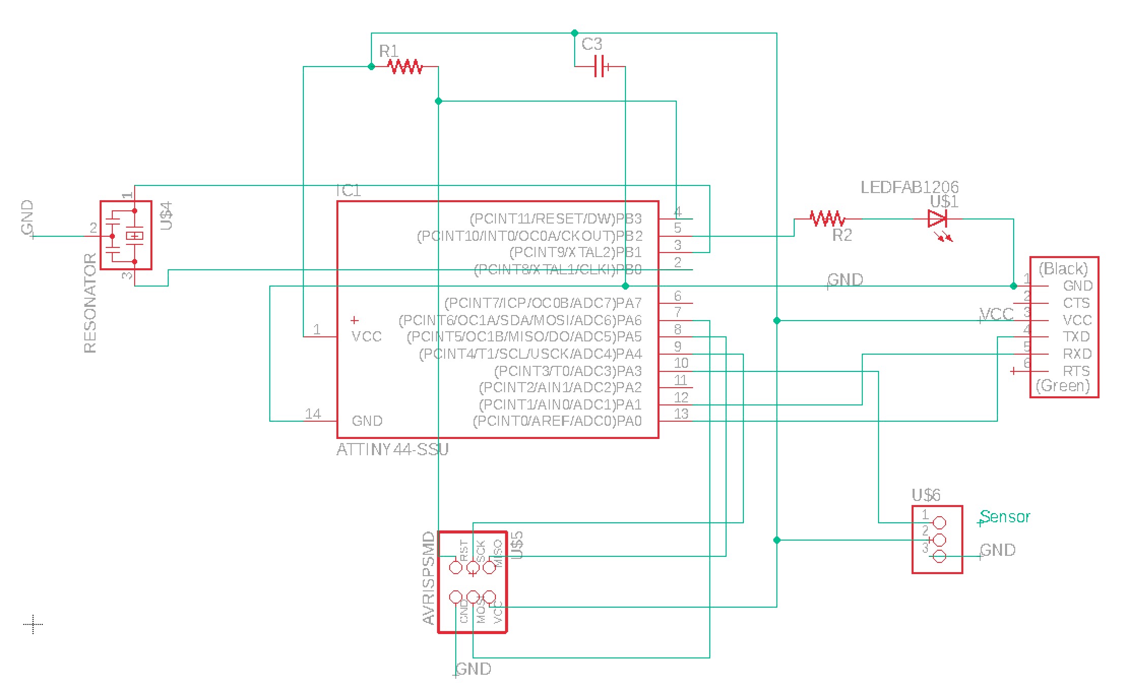
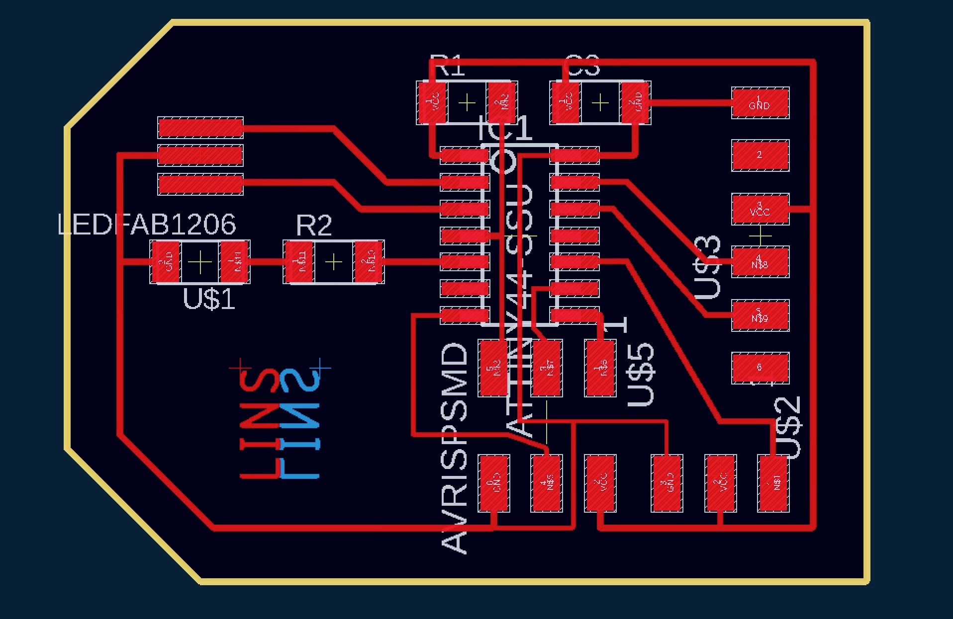
For Input Devices week, I am motivated to work with a heart rate sensor. As references, I have found past How to Make (almost) Anything Student student Oscar Rosello’s site and Github documents from the PulseSensor I purchased to be extremely helpful. The first step was to design a new PCB. As a starting point, I adapted my PCB design from Week 05, removing the button as well as an LED and resistor pair and adding a three-prong component for connecting the PulseSensor to. I was mindful to make sure the three-prong component was placed relative to VCC, GND, and PA3, an analogue to digital (ADC) pin.
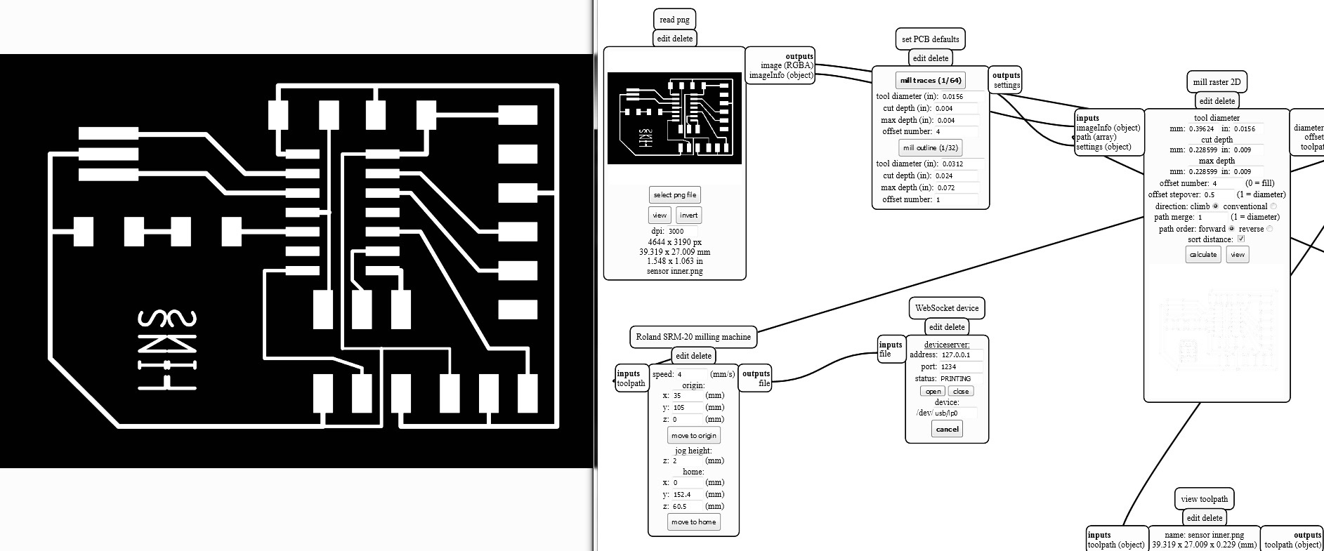
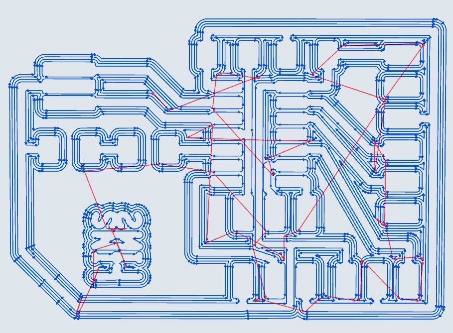
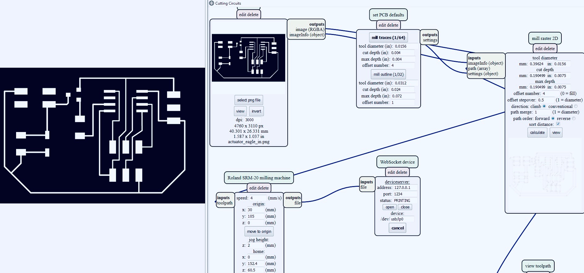
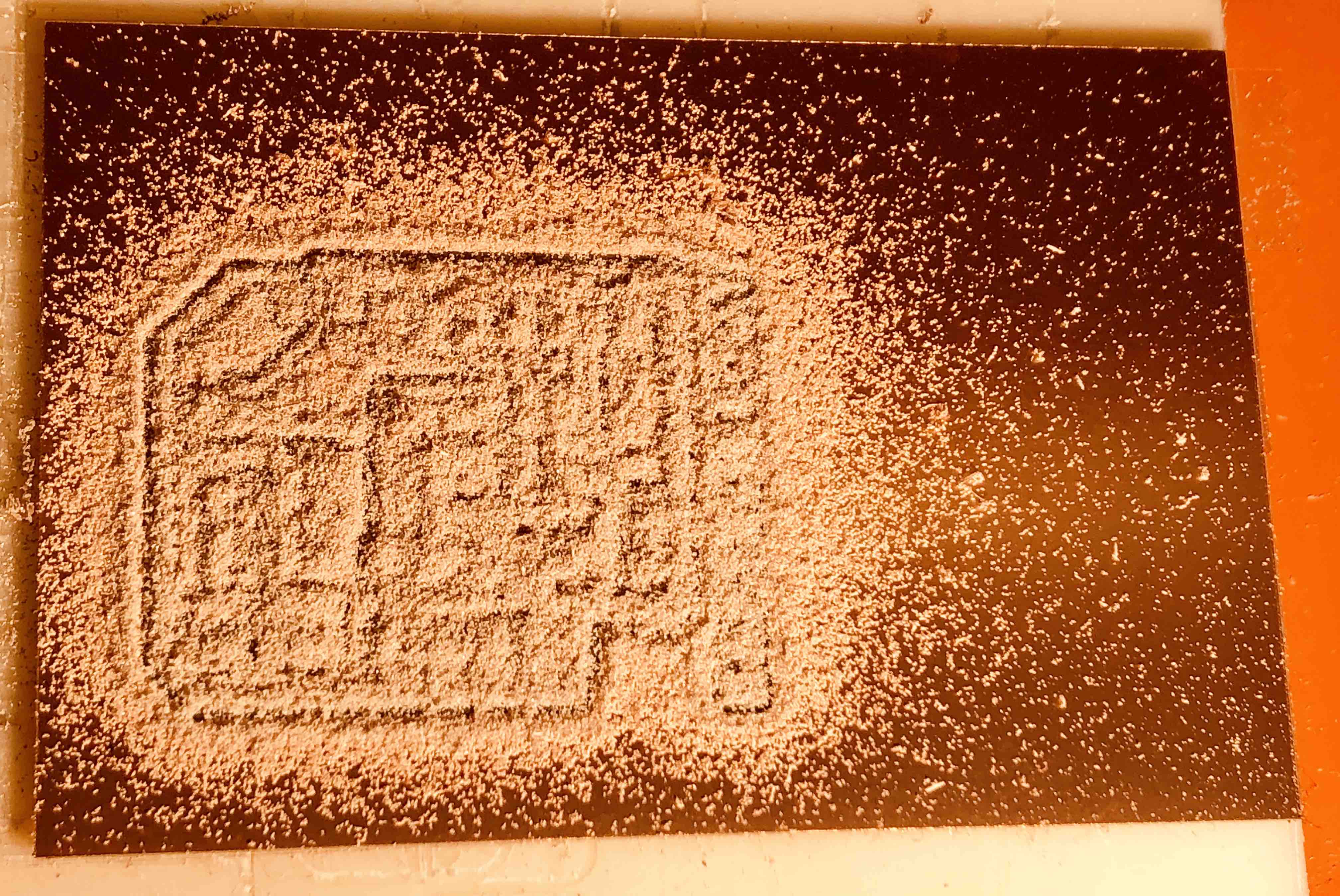
This is the third assignment requiring work on the SR20 mill and with each one, the setup and running of the mill becomes easier. The mods software provided by our professor Neil Gershenfeld makes all the difference as it has automatic settings for the spindle speed, feed rate, cut depths, etc. Plus, it generates the tool-paths for our imported designs. To account for Mac’s glitch when exporting images from Eagle, I doubled the DPI to 3,000 and also increased the cut depth to .009 when milling with the 1/64 inch bit.
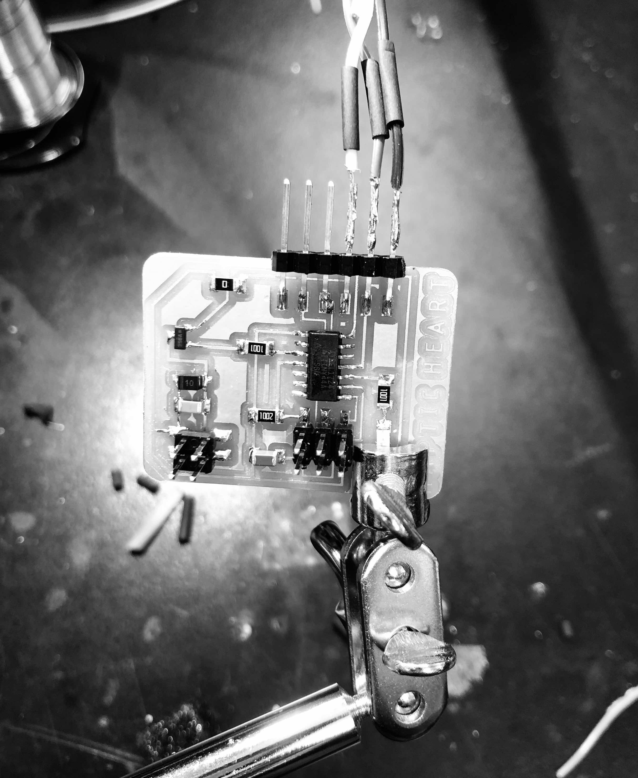
For the soldering, I continued experimenting with the reflow technique of dabbing solder onto the copper pads then reheating it with the air gun before placing the components down with tweezers. I was a bit conservative though in the reheating process as I was concerned about frying my components with the air gun. This caused my ATTiny to barely adhere to the mounds of solder which should have been more like puddles of liquid metal. After discovering the board did not work properly and a lot of trouble shooting with Rob, our Section leader, we made this realization. On a positive note, through the trouble shooting process, I learned a lot about how to use the Meterman, best connect my PCB to the computer, fine tune the settings in Arduino, and translate the appropriate ATTiny 44 pin number from the Datasheet to the Arduino specific pin number.
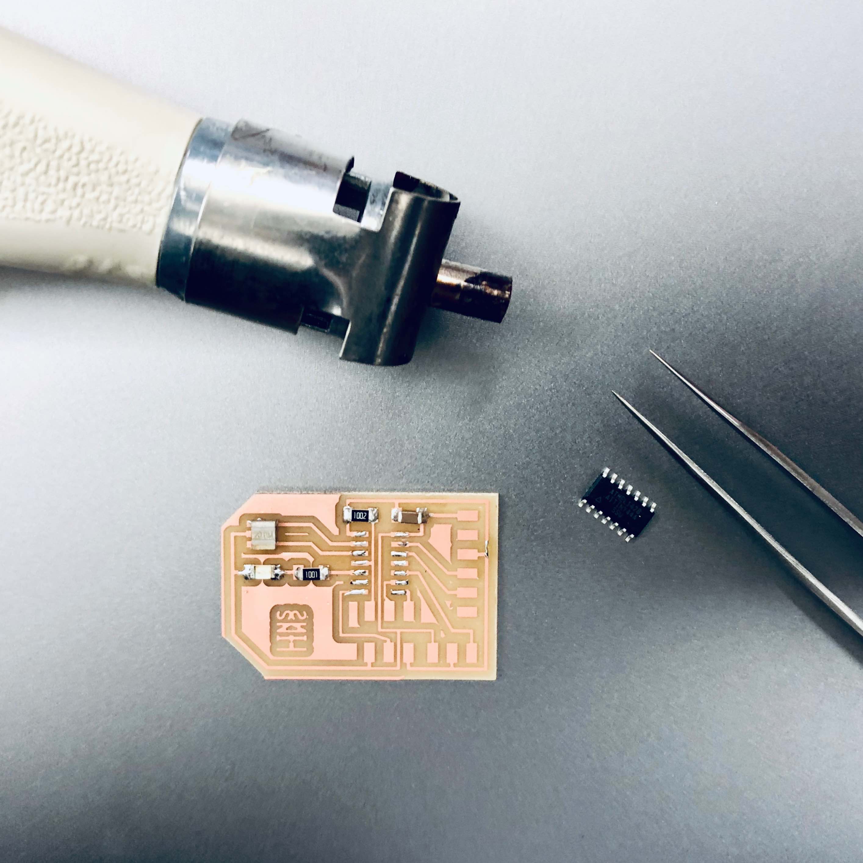
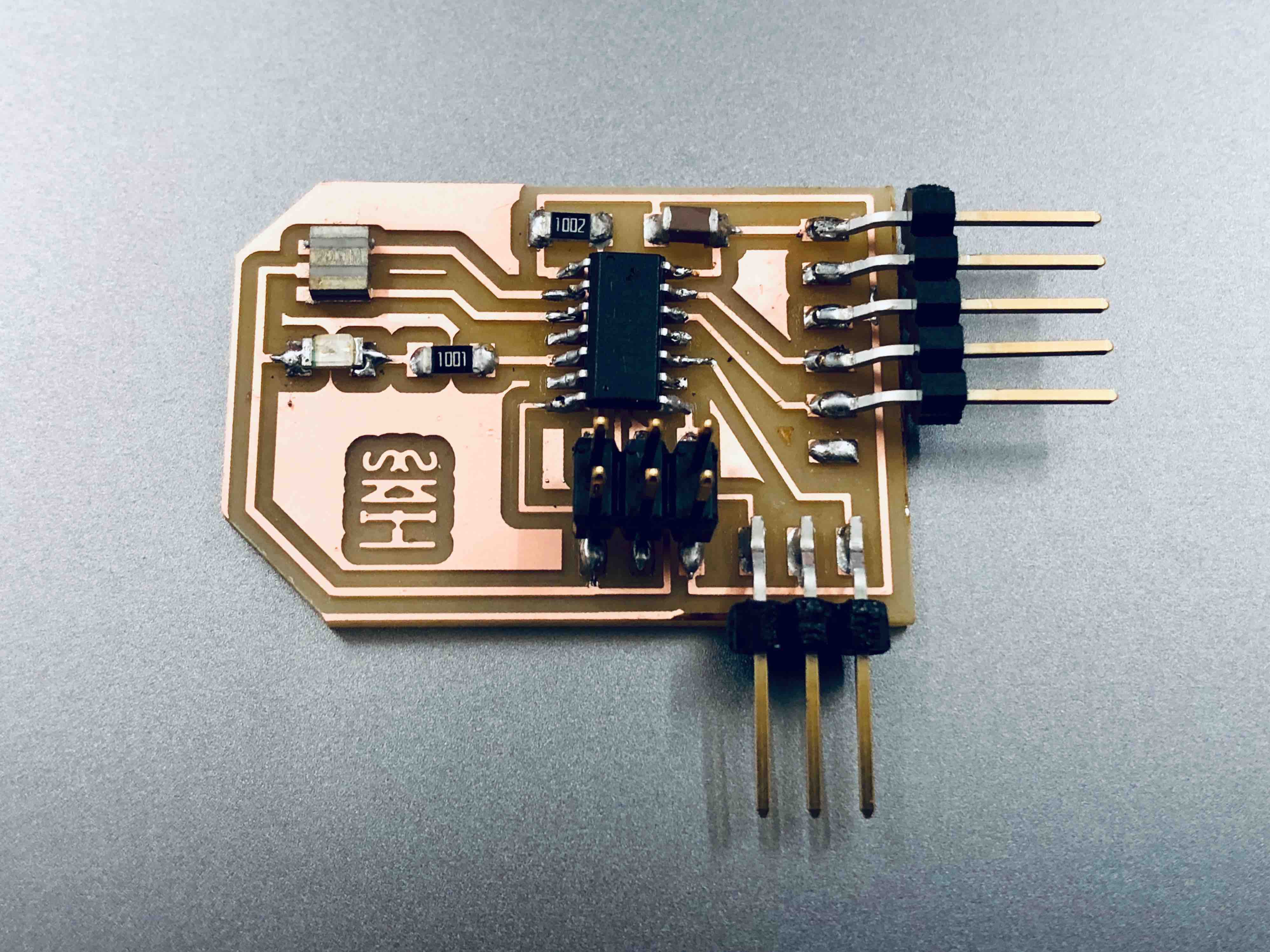
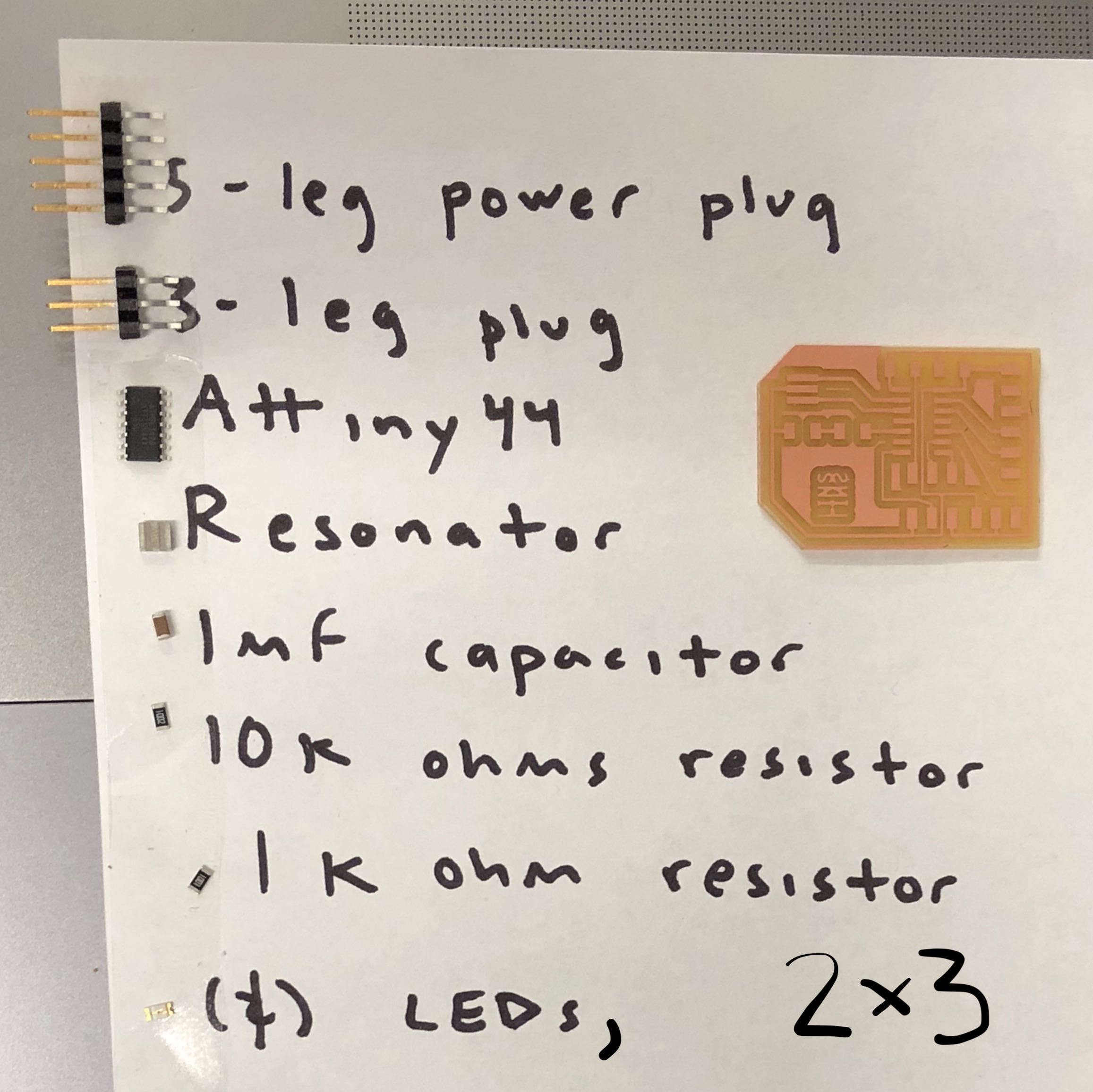
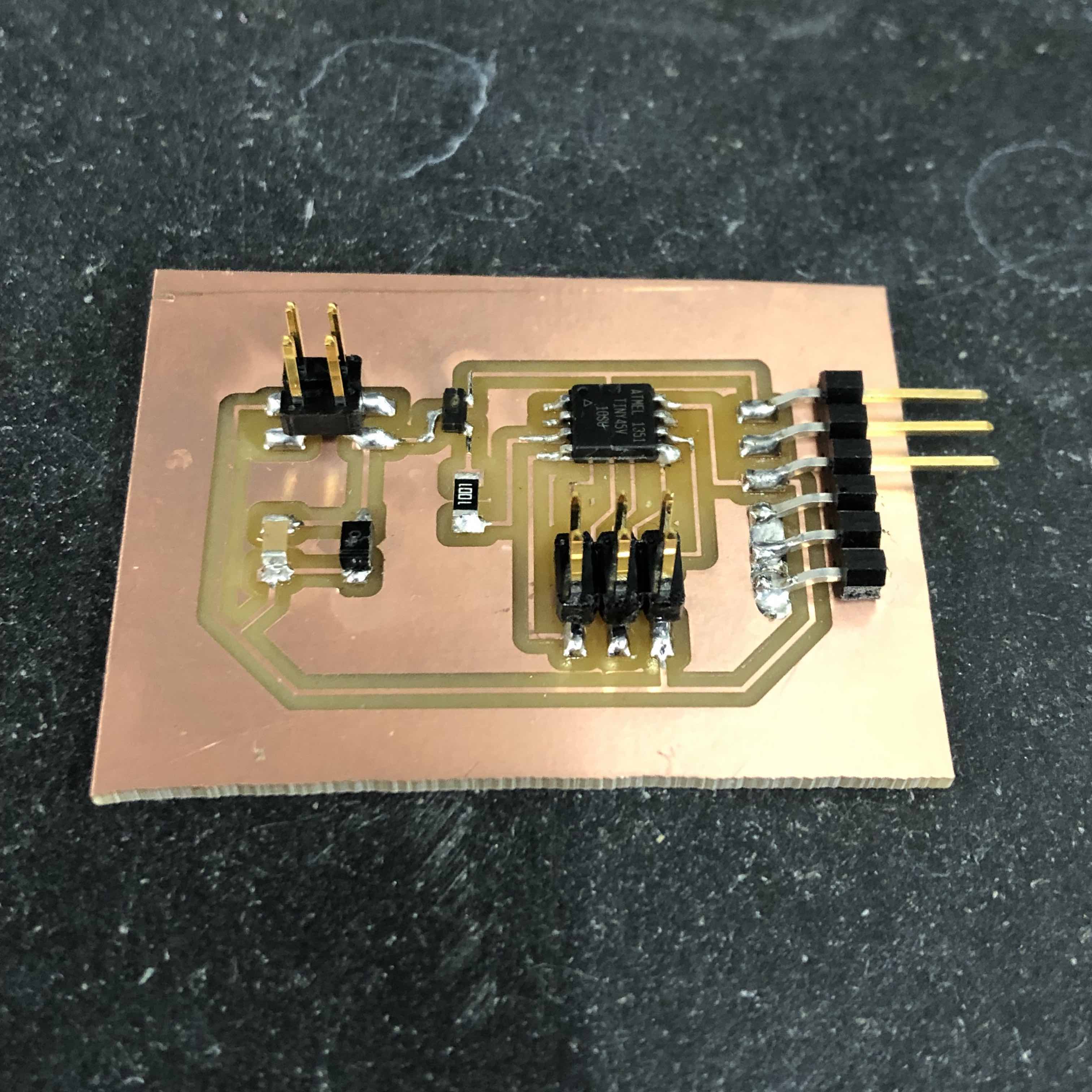
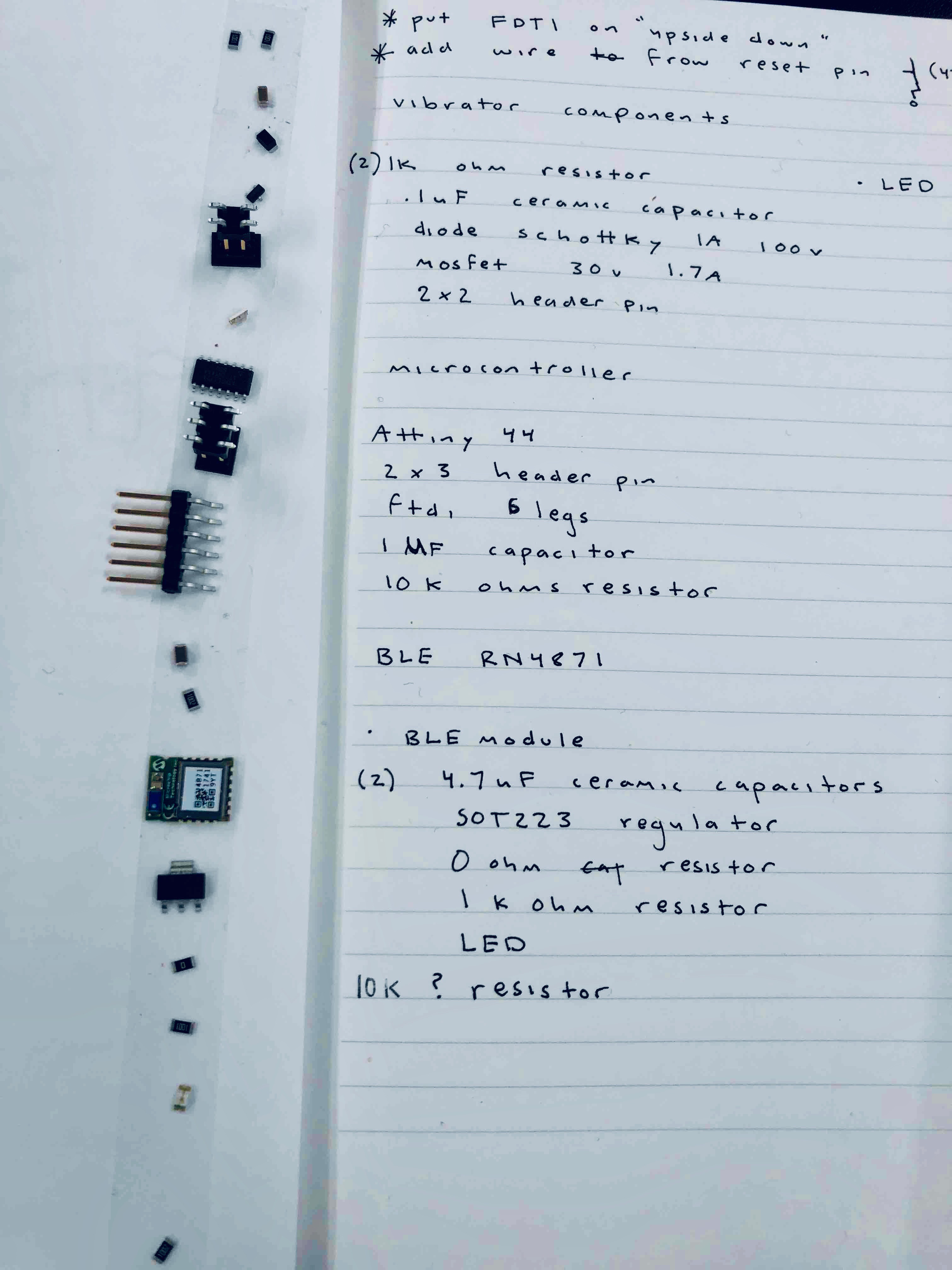
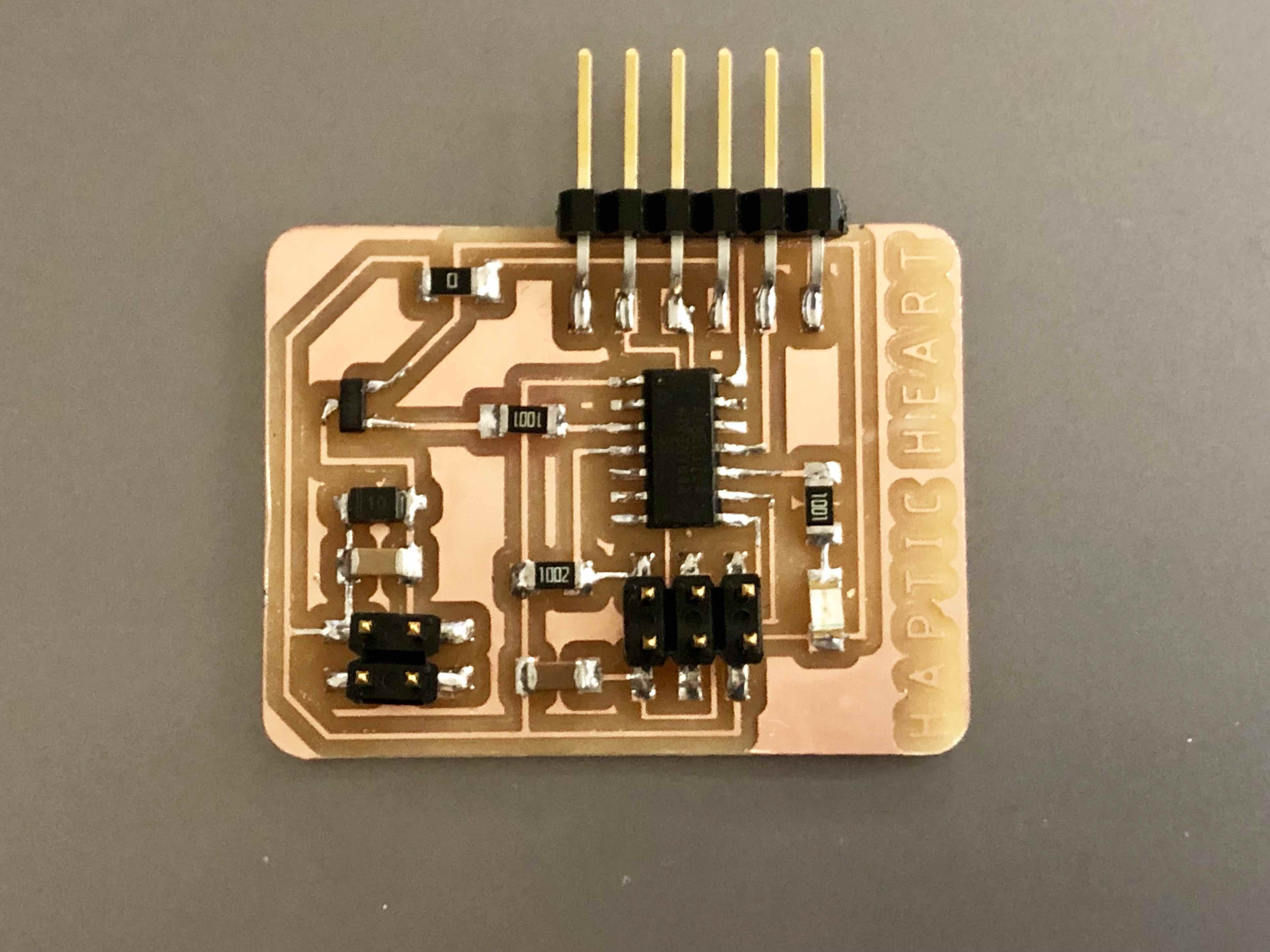
Here are the components that went onto the sensor board:
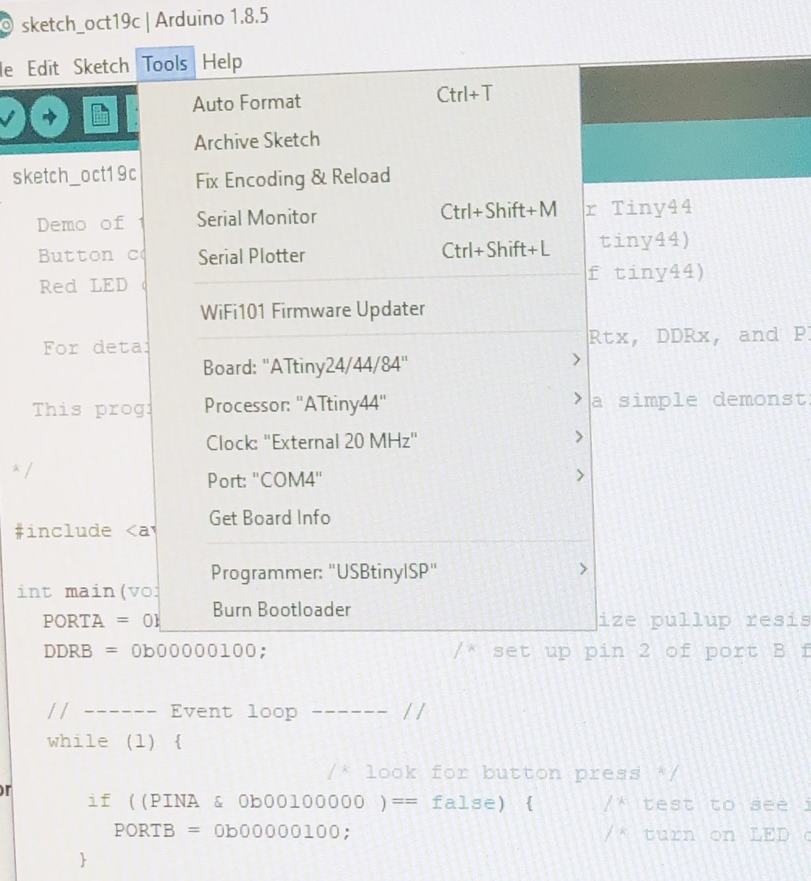
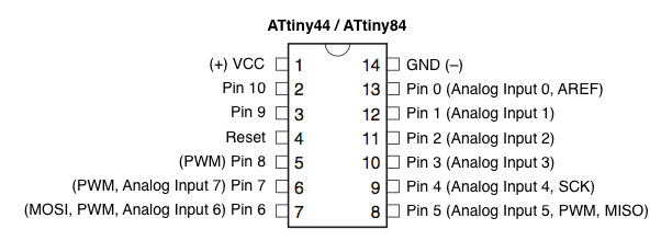
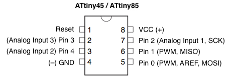
The PulseSensor I purchased from SparkFun came with some starter Arduino code. The real challenge was to figure out how to use code written for an Arduino board on a self-made AVR board. After using two incorrect diagrams, I recalled the one in the High Low Tech tutorial which worked beautifully. Be watchful to read your schematic and board view accurately before looking at the diagrams below to figure out the corresponding Arduino pin numbers.
Translation of ATTiny pin numbers from the Datasheet to the Arduino specific pin numbers:
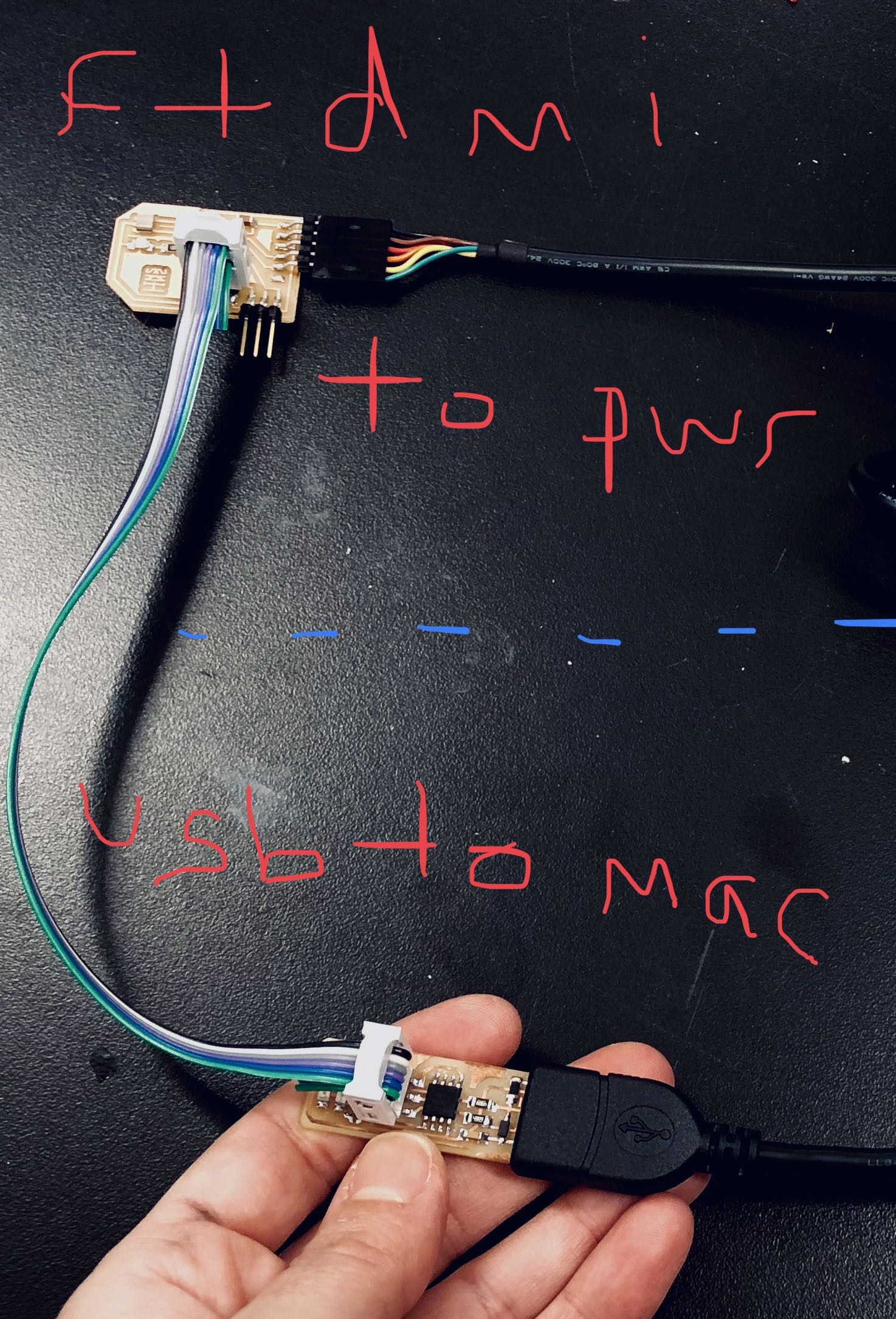
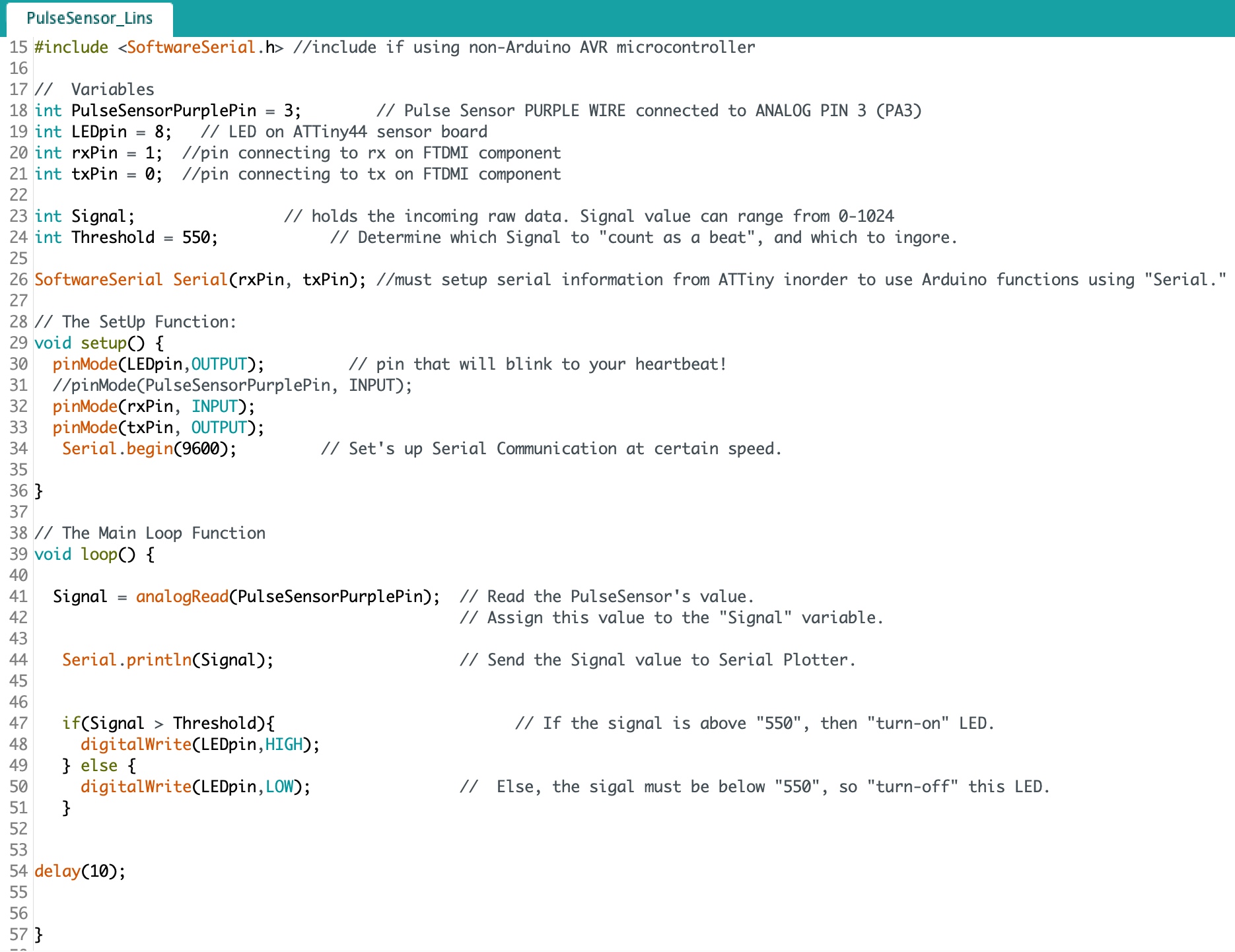
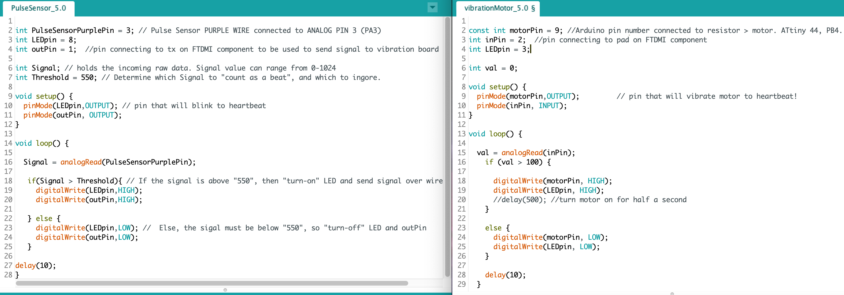
The next coding challenge was figuring out how to setup the serial information needed so that my sensor board could communicate through the FTDMI cable bi-directionally with my computer. In the photo of code below, read the //comments for more details:
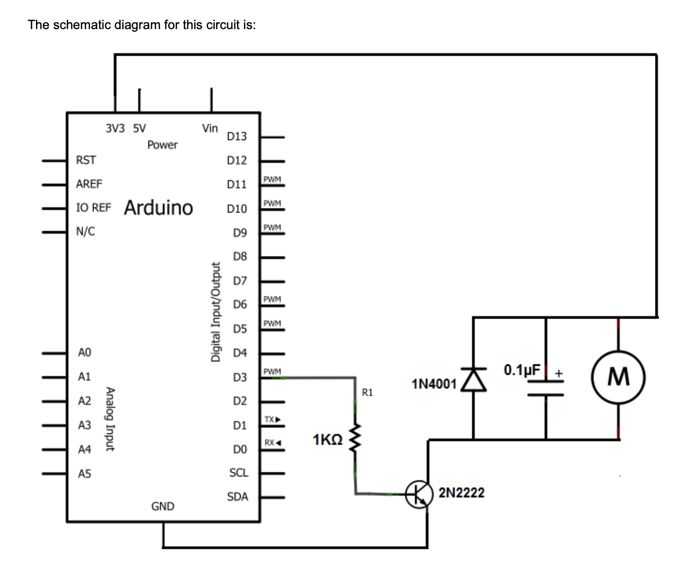
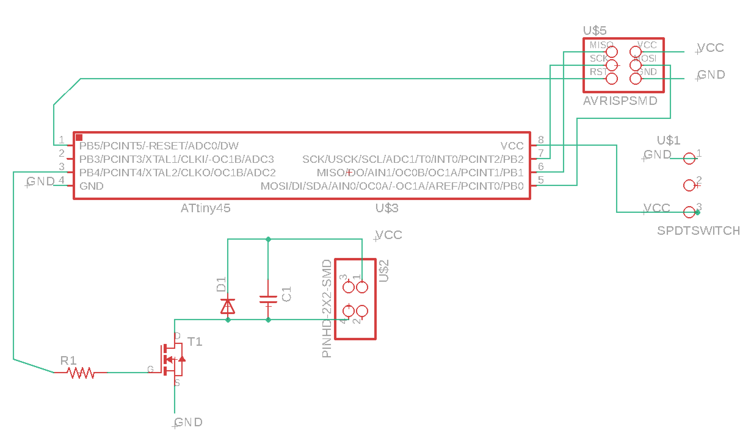
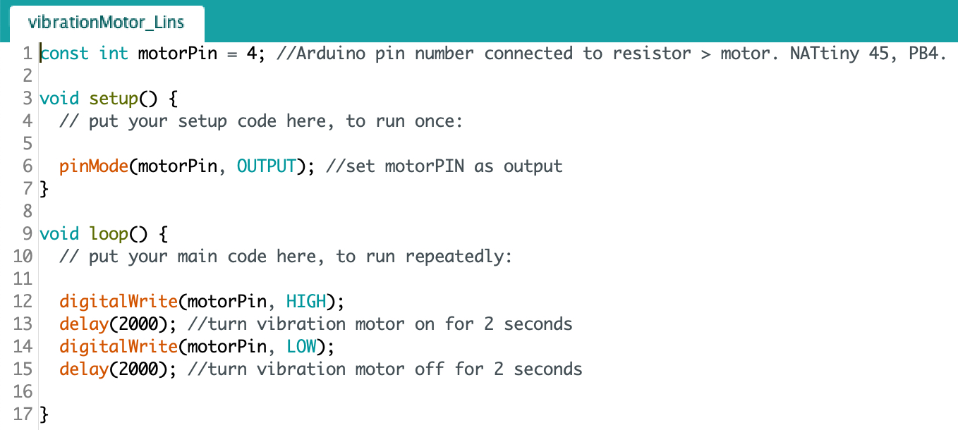
Building on my final project concept of making an abstract haptic heart that vibrates in accordance to my actual heart rate, I decided to design an actuator PCB for programming a mini vibration motor. I ordered a pack of motors from Amazon and found a useful tutorial online titled “How to Build a Vibration Motor Circuit.” The best part about the tutorial was its list of components and schematic for connecting them to an Arduino board which I was able to reinterpret into my own design. Not working with an Arduino, I added to the list an ATtiny 45 as the microcontroller, a 2x3 header pin for programming, a 2x2 header pin for connecting the motor, and an FTDMI connector for power. With Rob’s assistance, if I wasn’t able to find the exact component in the shop, I found an equivalent one to work with. As before, I used Eagle for the PCB design and the SR20 mill in the Harvard Science Center for machining it. Having gone into some detail last week regarding a similar design, fabrication, and coding process, I will be more brief this week. Please refer to the Input Devices Week for more nuanced information like cutting depths and Arduino pin number translation.
Below are screen shots from the “How to Build a Vibration Motor Circuit” tutorial (http://www.learningaboutelectronics.com/Articles/Vibration-motor-circuit.php):
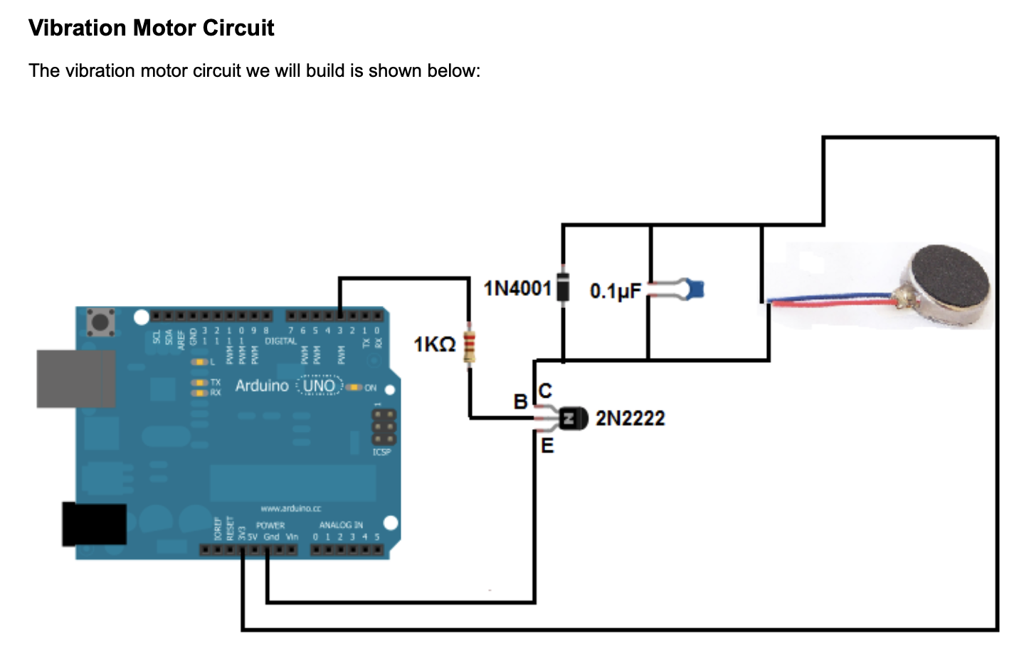
The list of parts I used:
- 1K ohm resistor
- 0.1uF ceramic capacitor
- diode schottky 1A 100v
- mosfet 30v 1.7A
- ATtiny 45
- 2 x 3 header pin
- 2 x 2 header pin
- FTDMI connector
Two things went wrong in the design and soldering process. The first being, I had the rotation of the mosfet incorrect and second, the FTDMI connector, once soldered, broke off, taking with it the copper pads and traces it was attached to. While I was able to manually rotate the mosfet during the soldering phase, I could not salvage the FTDMI connector mess. My attempts to add wire where the copper traces had broke off, failed.
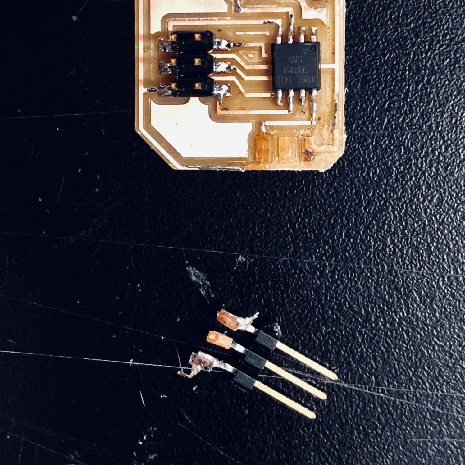
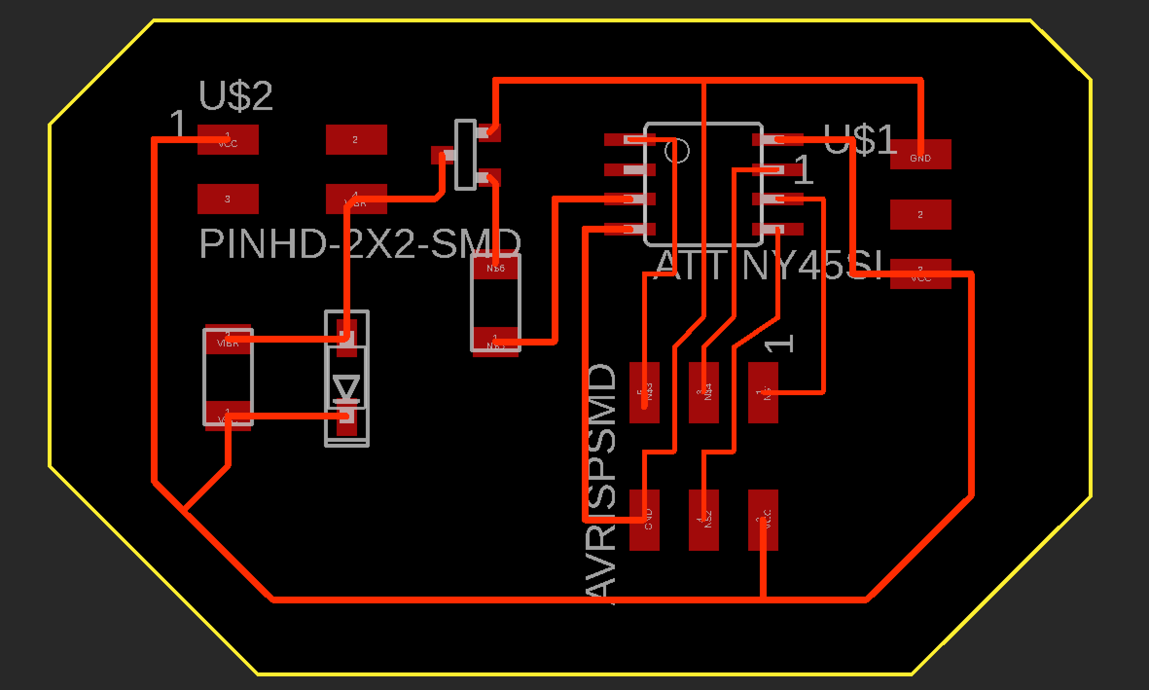
To prevent the above from happening again, I corrected the mosfet orientation and connections in my Eagle schematic and added more distance between the traces and outer boarder. This way the FTDMI connector had more padding to rest on and the traces couldn’t be so easily peeled up. Regarding the mosfet, keep in mind that the Drain goes to the motor, the Gate to the microcontroller, which in my case was via a resistor, and the Source to ground.
Prior to when the FTDMI connector broke off, I was able to briefly test the vibration motor by touching its two wires to the appropriate soldered pads on my board, at which time, the motor vibrated instantly. Though my new board came out better, so I thought, the motor did not respond in the same way. Programming it didn’t help either.
After scrutinizing the board with the Meterman and Rob and replacing the mosfet as a result, the motor began vibrating as before. Unfortunately, it was unresponsive to programming and upon replacing the ATtiny 45, I again tore off a trace and was forced to stop. My plan is to return to this project during networking week.
 Here is a recap of Week 13 where I redesigned the sensor and actuator boards in order to augment them with bluetooth capabilities...
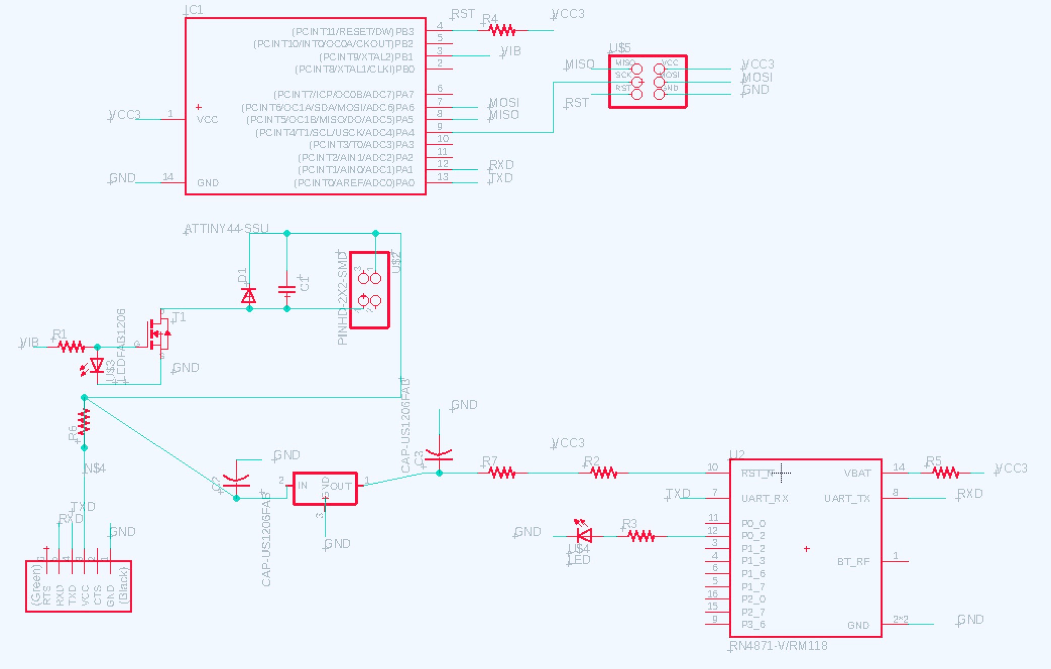
I began this week’s assignment with great ambition, seeing it as an opportunity to make great progress on my final project. For my Haptic Heart project, I will need to connect wirelessly my heart sensor board and mini vibration board so that as I dance, my heart beat will be felt via a matched vibration in the silicone heart held by an audience member. Since I was never able to get my mini vibration board working, I thought I should begin with a redesign of this board to check for errors and to make the addition of a BLE module. I selected the RN4871 module.
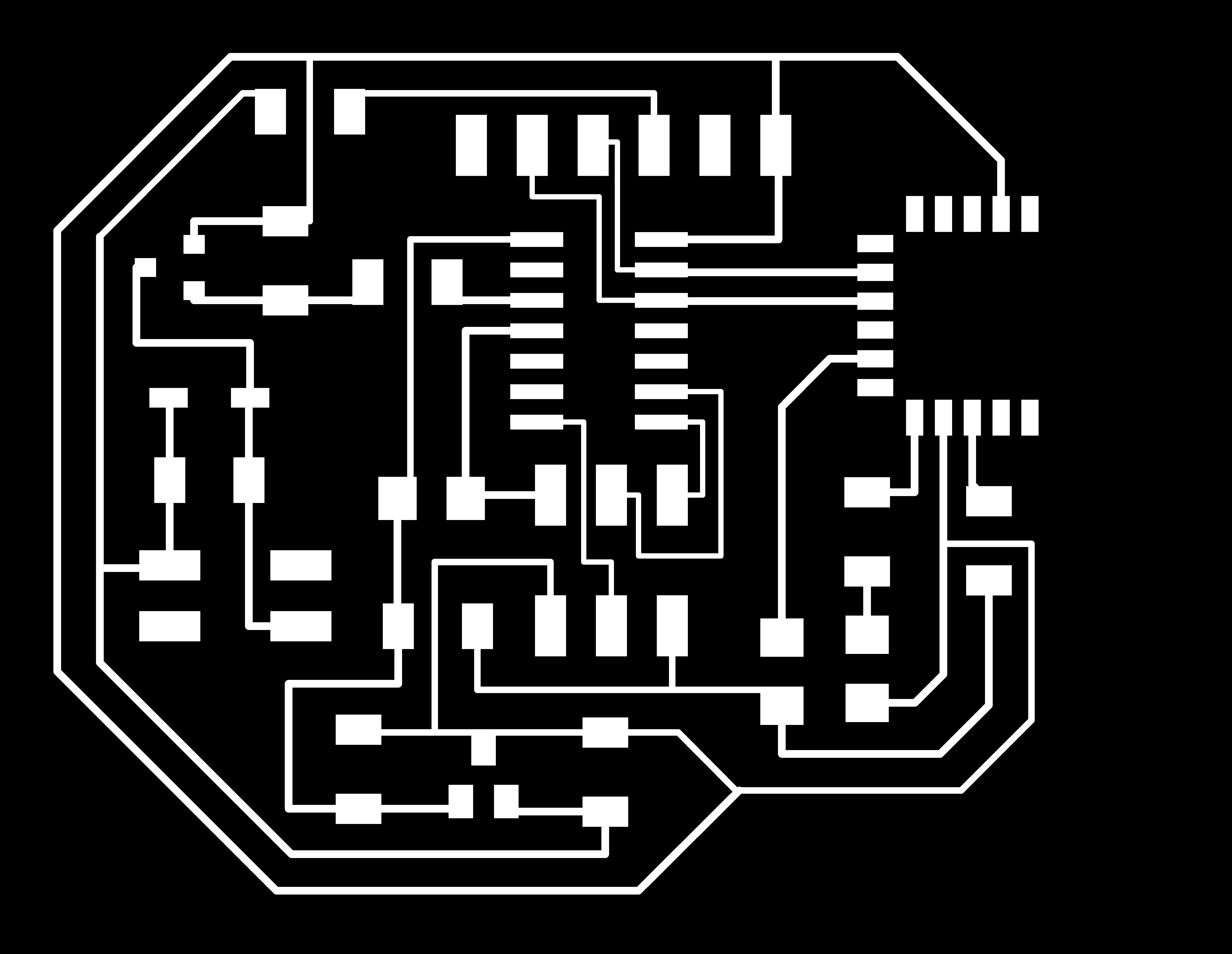
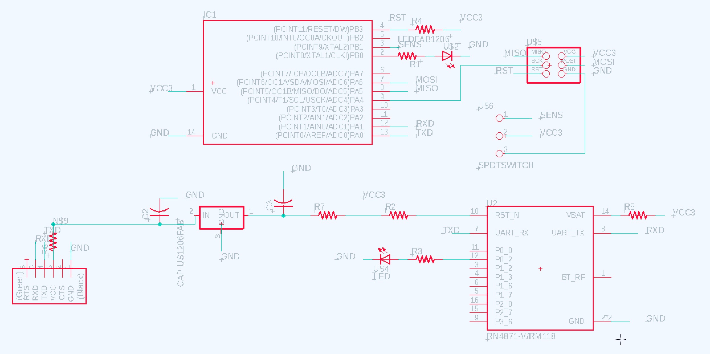
I began by replacing the ATtiny 45 with an ATtiny44 since my first version lacked enough pins to setup serial communication via the FTDI connector, a must for configuring the RN4871. Midway through the design, I noticed I did not have a capacitor or resistor connected to the FTDI VCC pin on my previous schematic nor the reset pin on the 2x3 header connected to the reset pin on the ATtiny. Perhaps this is why my last board did not program! It was quite a challenge to include the sequence on components necessary to support the ATtiny44’s programming and serial communication, the vibration motor, and the BLE module. Sorting through the rat’s nest when switching from the schematic to board view in Eagle is always a puzzle. That said, I made a few decisions I question…
I ran a VCC trace under a resistor. I added a zero ohm resistor along the VCC trace in a different area to allow GND to pass underneath. I added the SOT223 regulator just before the BLE module (including capacitors) instead of right after VCC enters the board from the FTDI connector. I have to plug in the FTDI cable “upside down” since GND is “south” instead of “north” in comparison with previous boards (not sure if the FTDI cable is happy with this).
Following Rob’s advice, I only soldered on the components relating to the BLE so I could test and debug this part of my board independently. Using Cool Term, an app for Mac that facilitates serial communication with BLE modules, I was able to put my module in Command Mode by entering $$$ in the terminal. But within minutes, the LED on my board went extremely dim and then I lost communication all together.
Of my concerns, the one that was an issue was the placement of the regulator, which in fact does need to be placed in immediate proximity to the FTDI VCC pin. This is because the ATtiny also needs to be running off 3.3 volts so that it’s RX and TX connections to the BLE are operating at the same voltage. Also, I made an amateur mistake and forgot to ground several capacitors on my board.
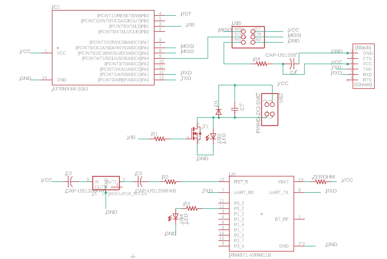
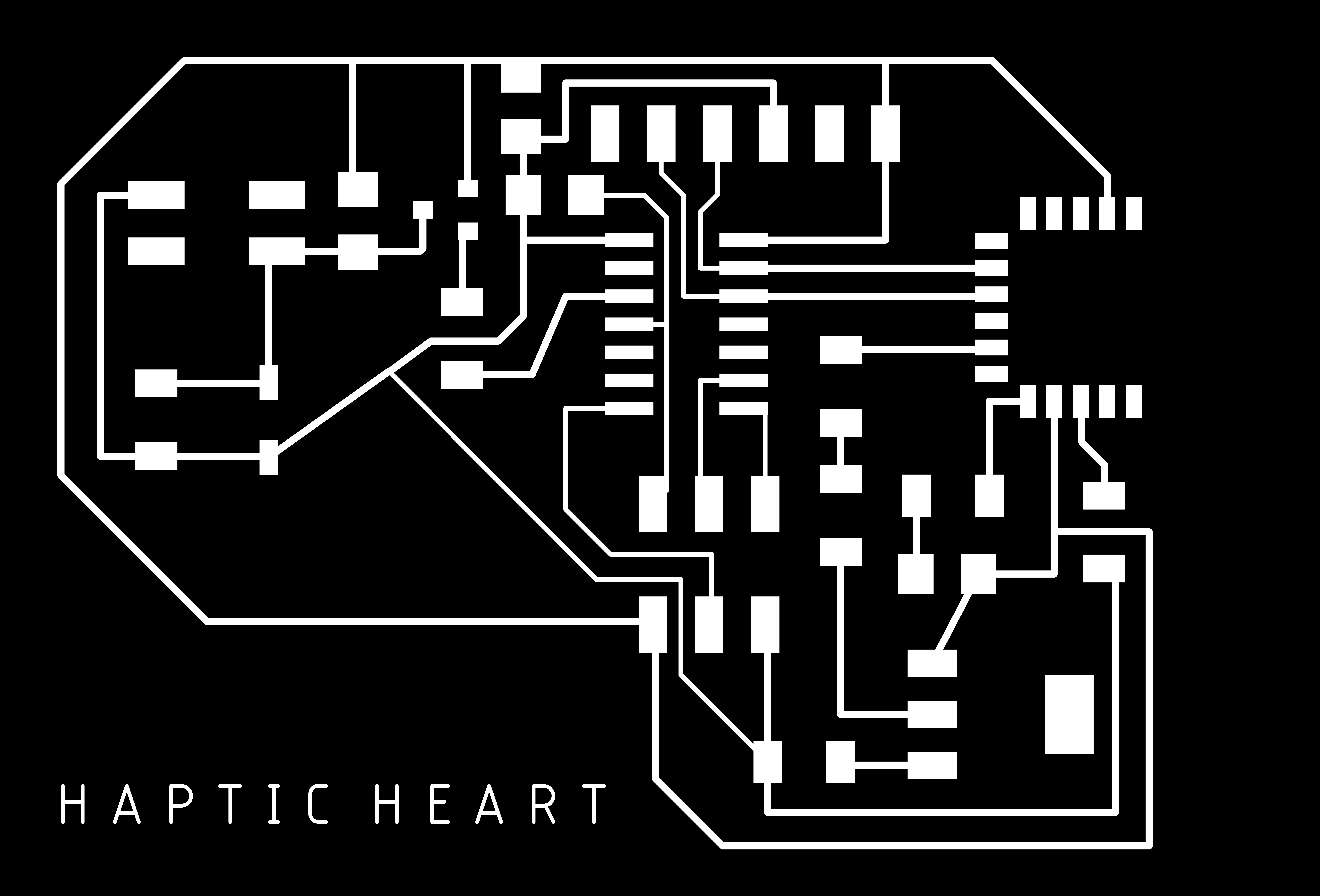
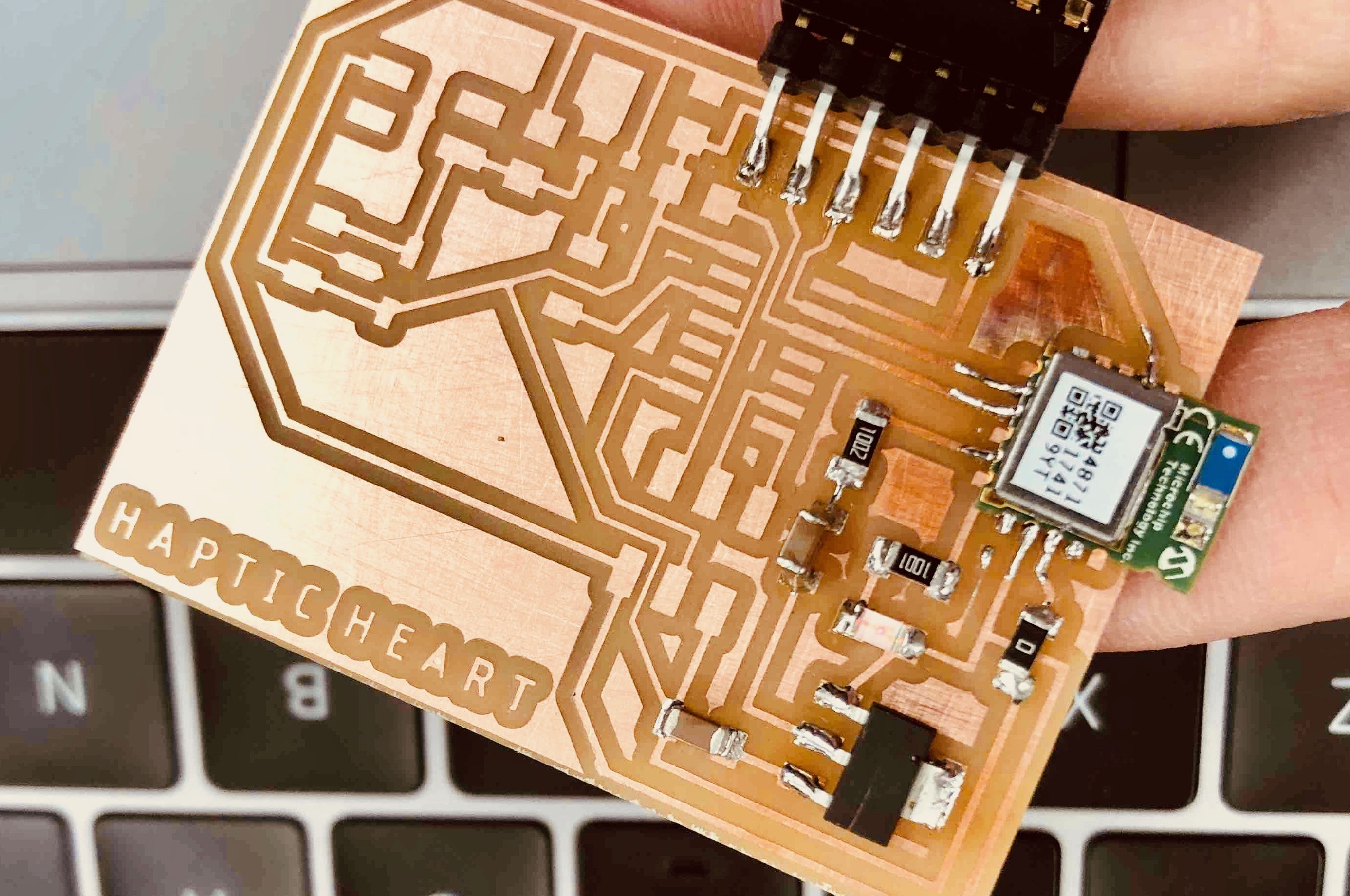
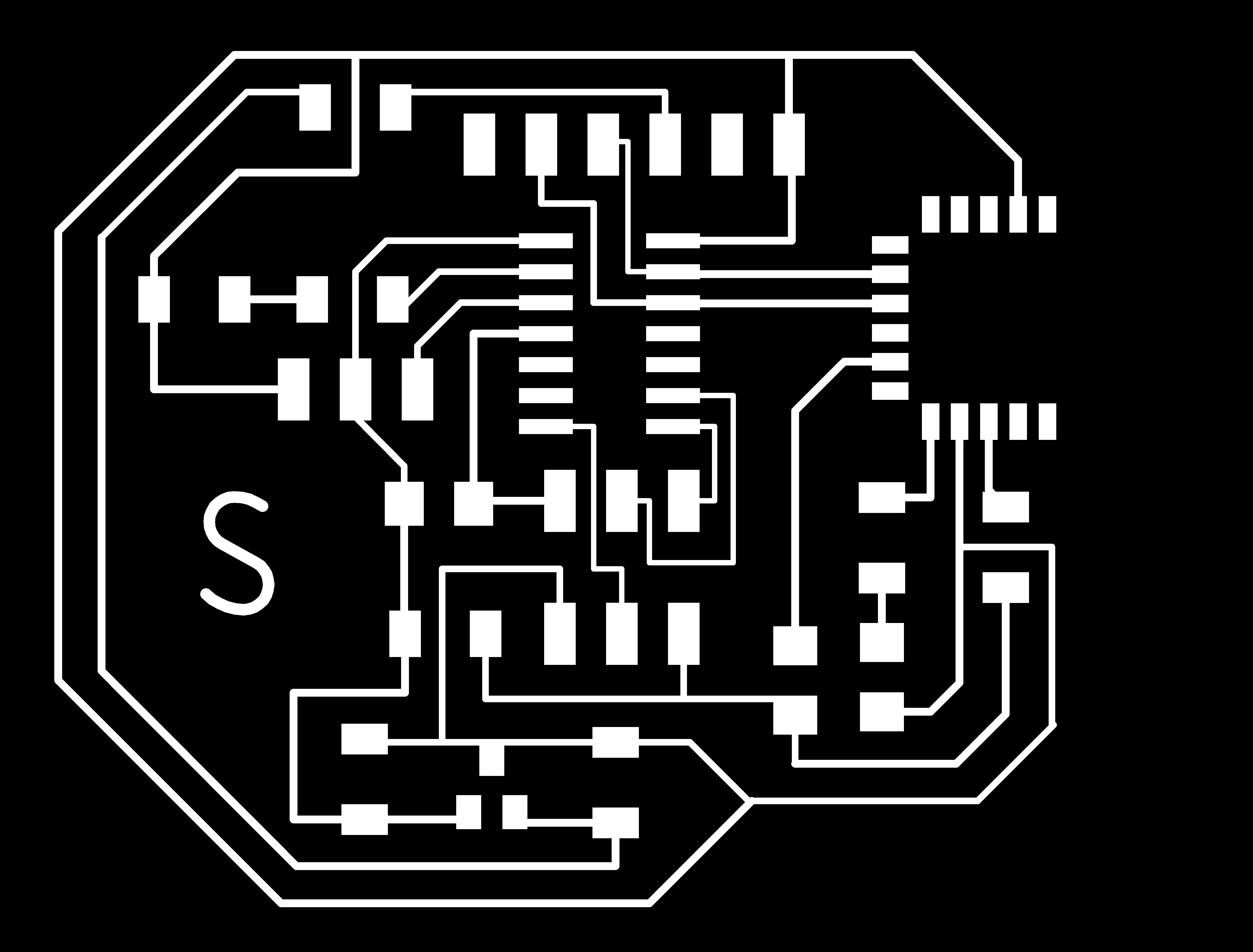
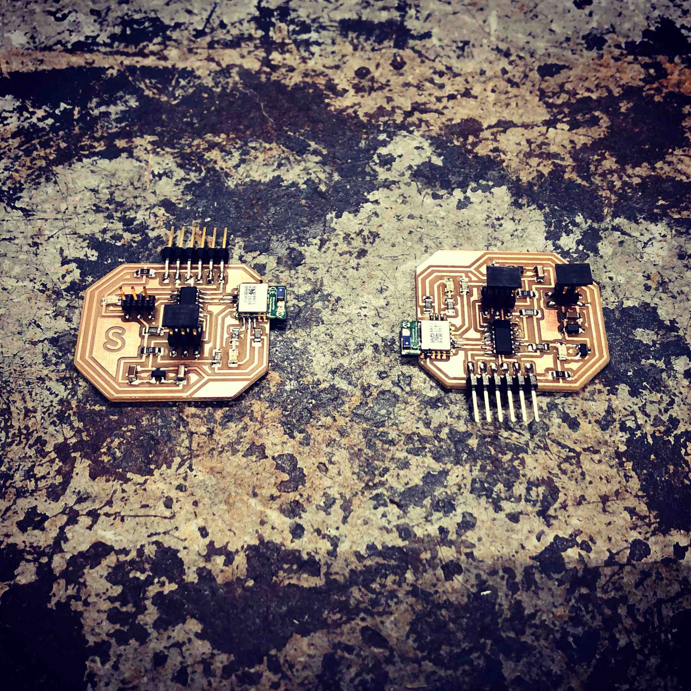
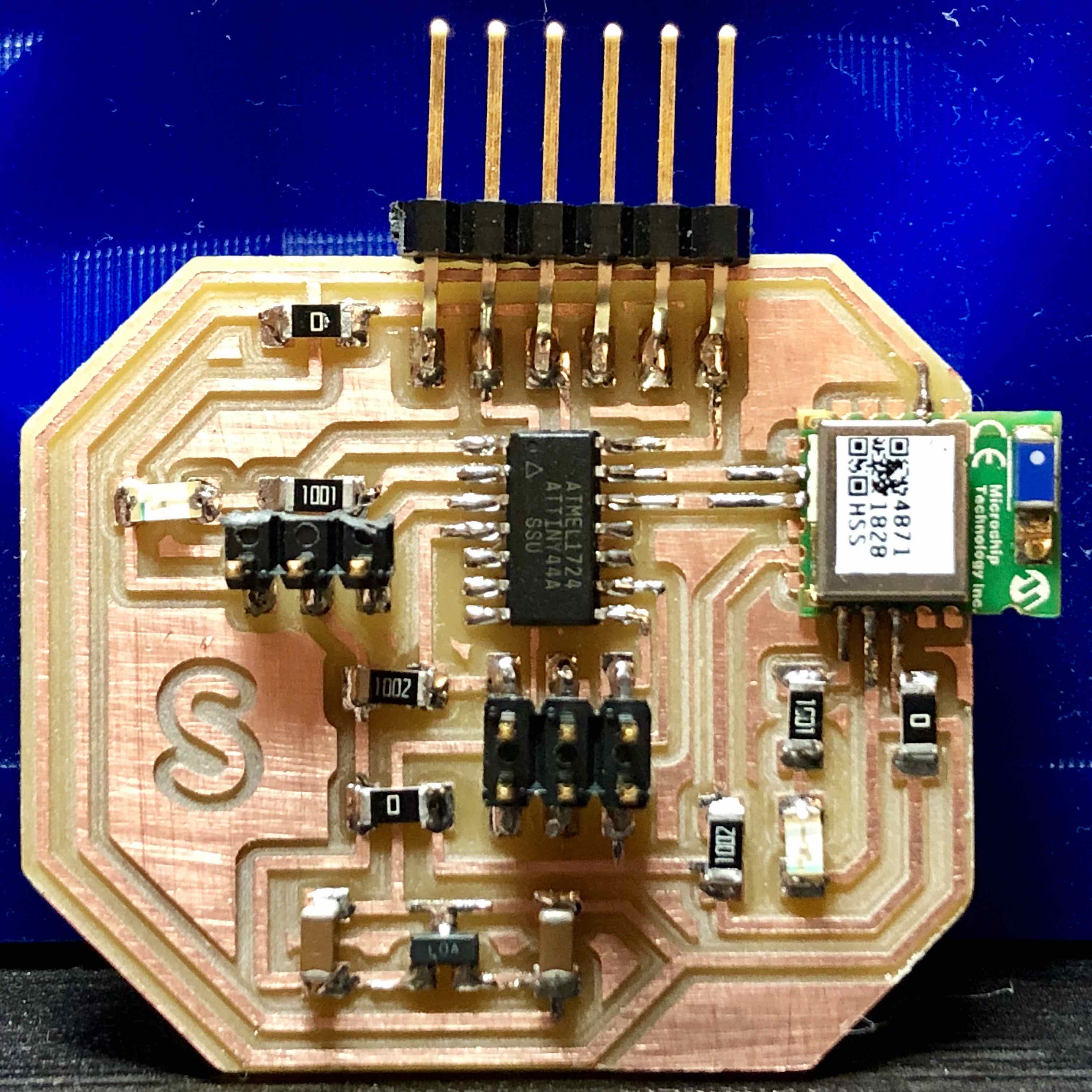
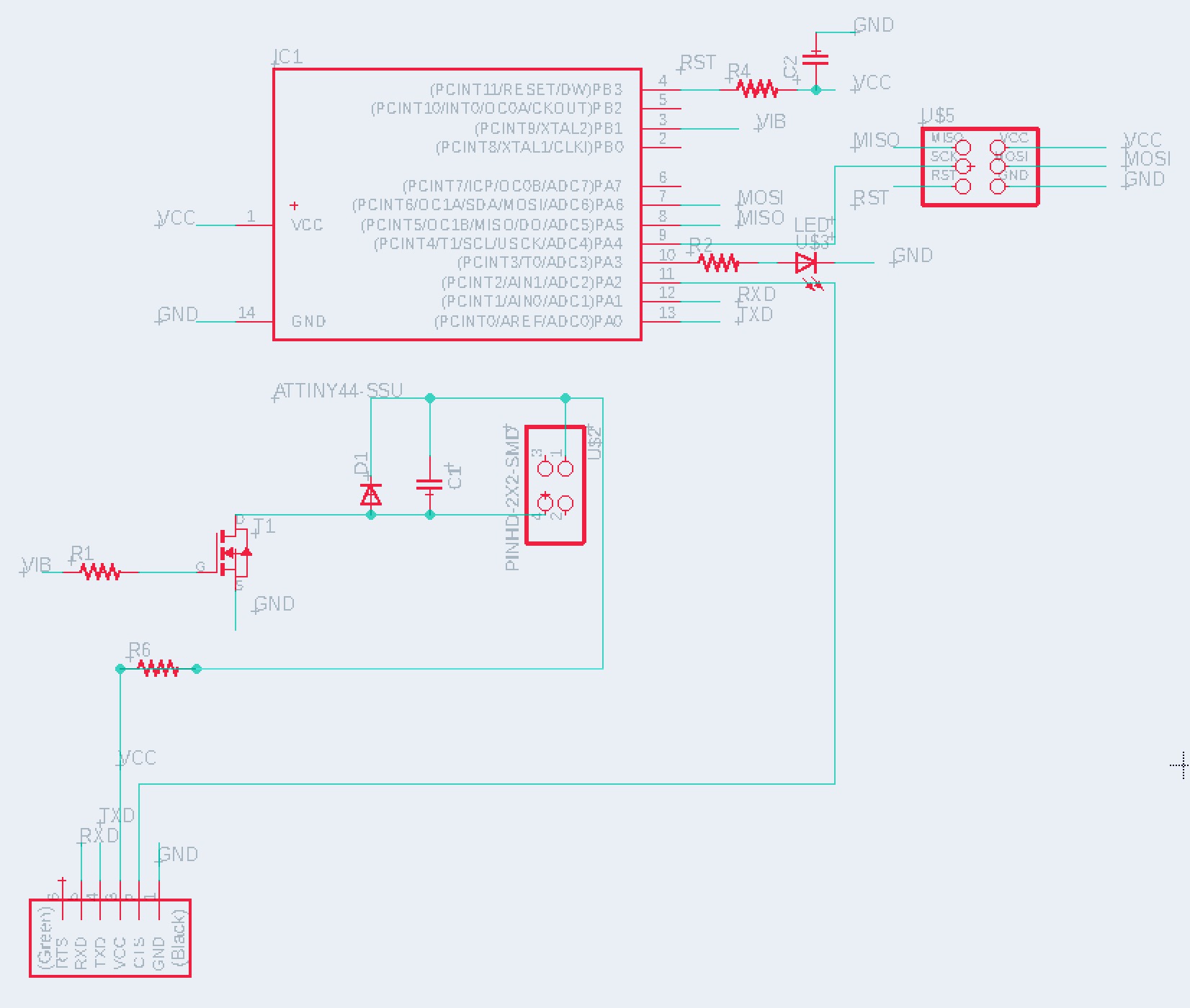
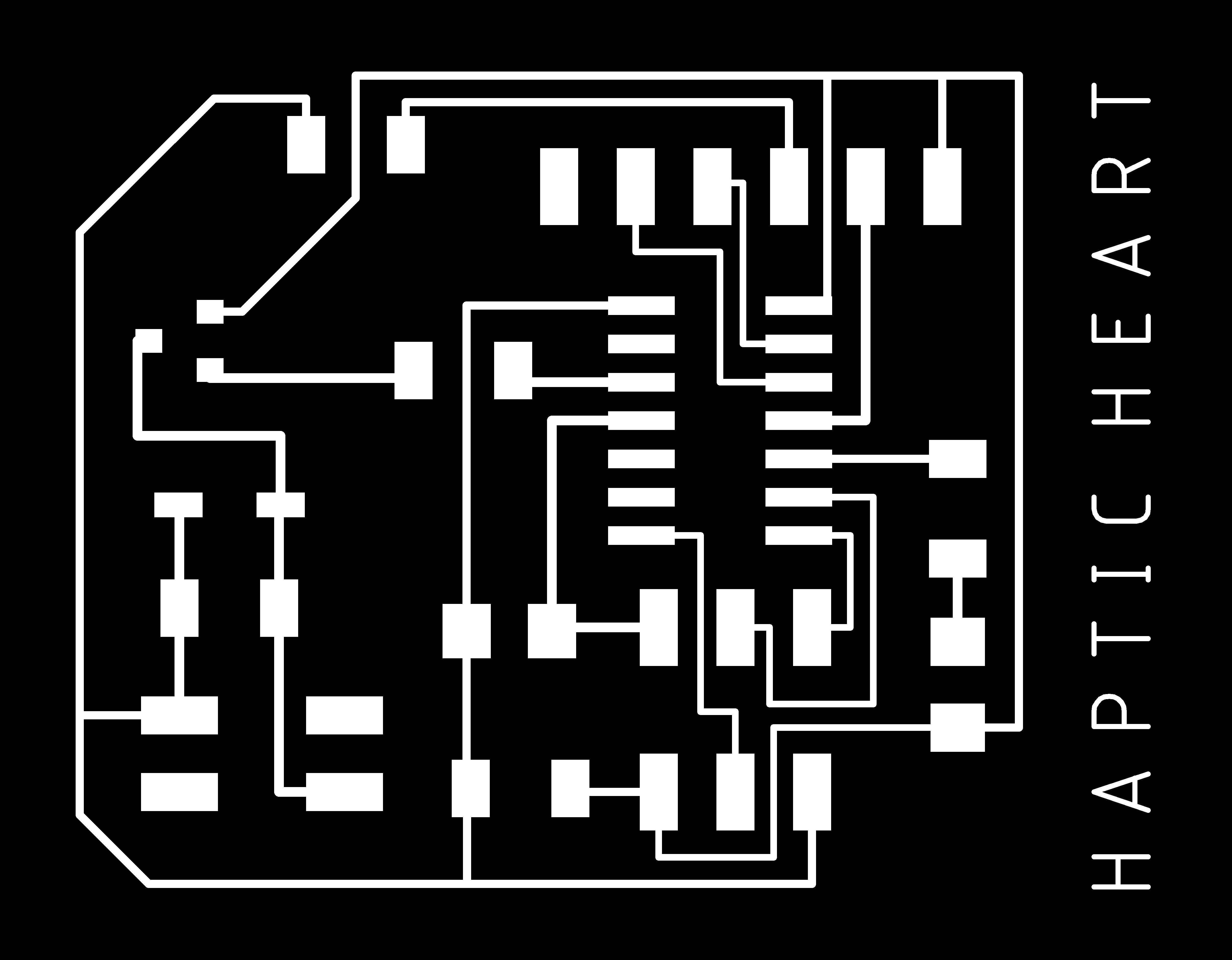
FBelow is the redesigned mini vibration board as well as the redesigned heart sensor board which was also expanded to include a BLE module. The main things to note is the new regulator setup that uses a SOT23 with 1.0uF capacitors on each side. The 3.3 volts the regulator produces is used to power both the ATtiny44 and BLE. 5 volts powers the motor prior to the regulator. Be aware, there are several 0 resistors on the board clearly seen in the close up photos of the finished boards (GND got trapped inside the many traces in several areas on the board). The Meterman validated the 3.3 volts post the regulator and both BLE’s were communicated with on Cool Term. Progress!
Actuator below
Sensor below
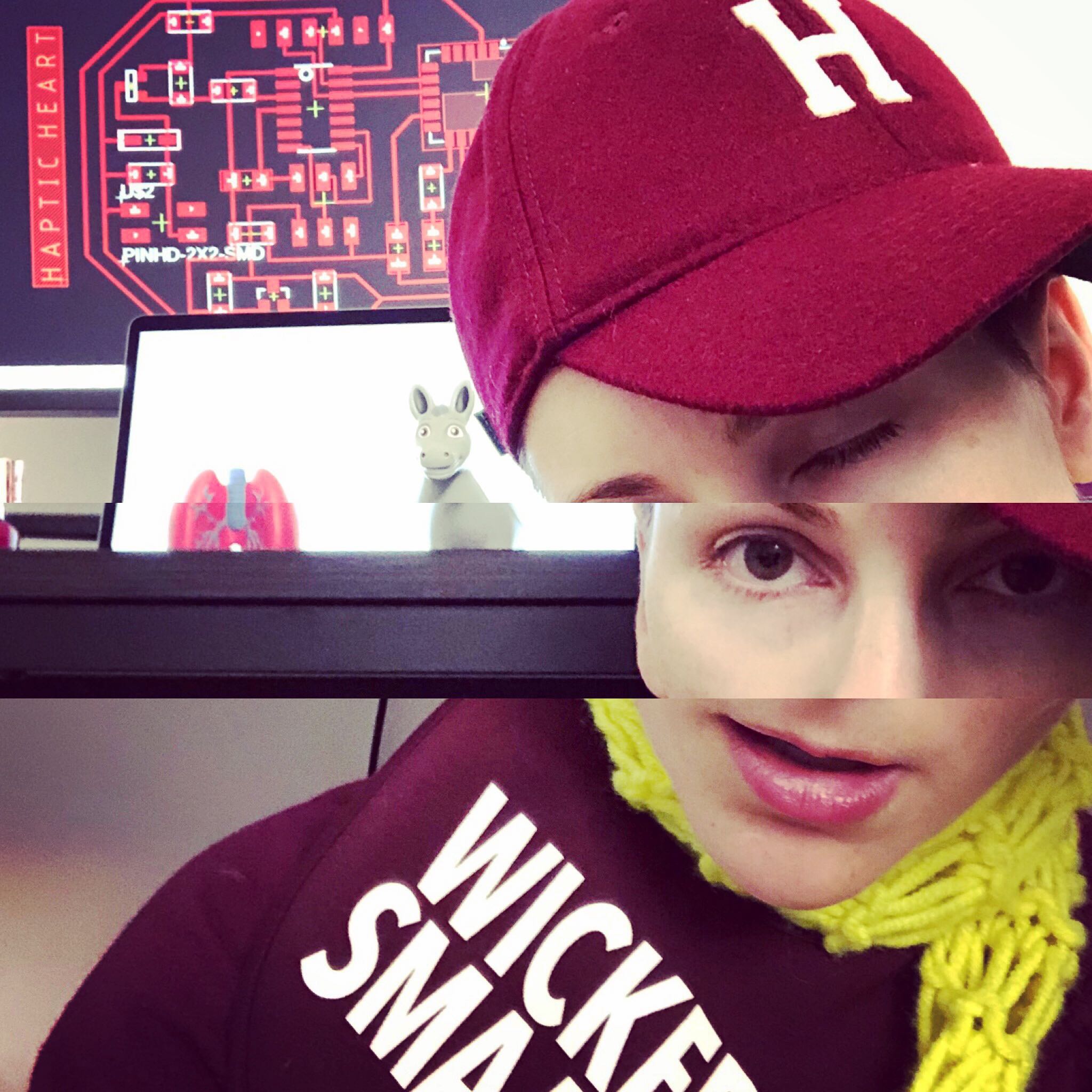
Delerius from 8+ hours on Eagle.
Sensor, left and Actuator, right.
Actuator below
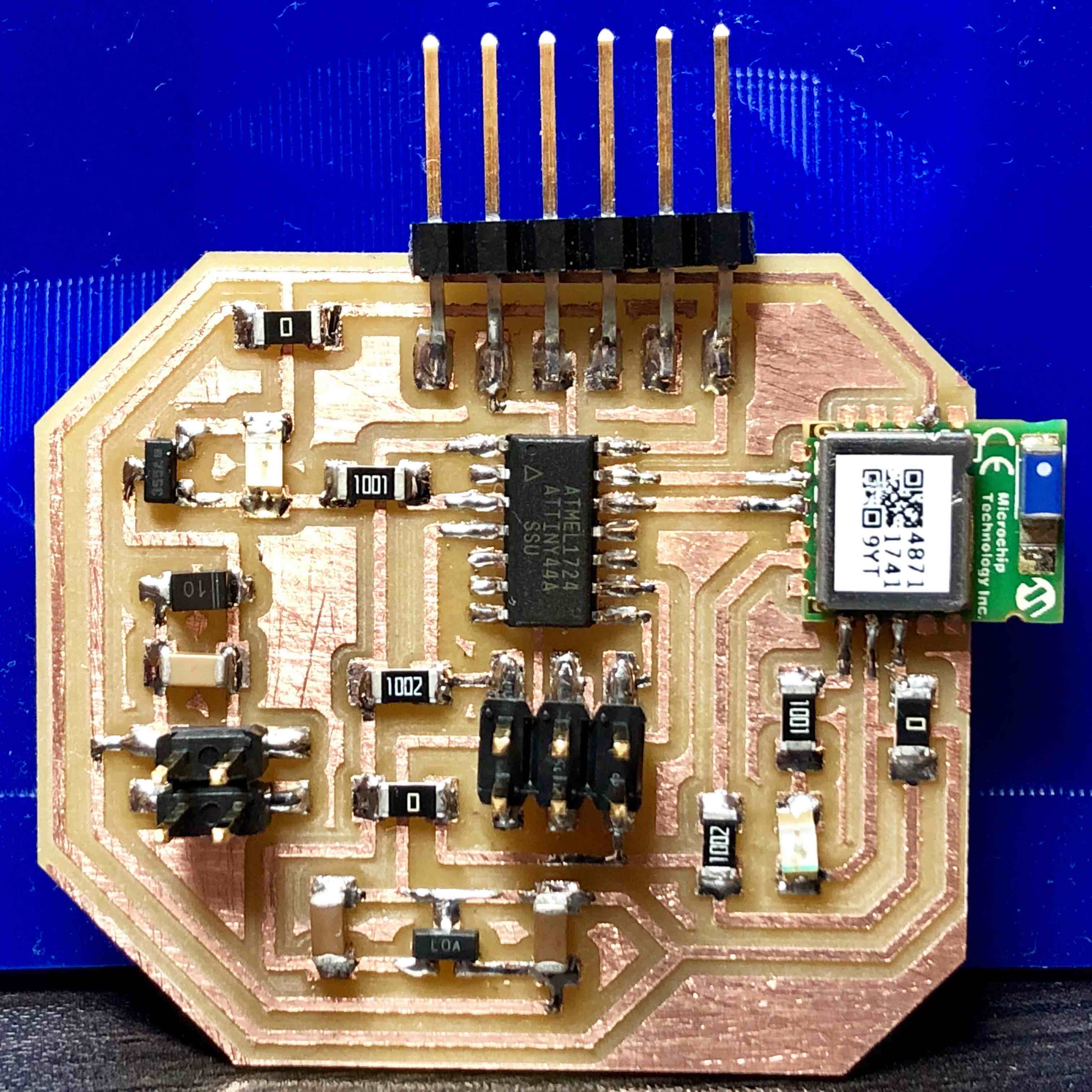
Sensor below
Before moving on to programming the two boards to communicate via Bluetooth, I began with programming them to each do their simple tasks - read the heart rate sensor/blink an LED and turn on and off the vibration motor at two second intervals. This turned into a full day of work as the coding process revealed further oversights in the board design. These were…
Sensor Board Boo-Boo’s- Heart rate sensor pin was not connected to an analogue read pin. Solution: jumper wire.
- BLE module LED indicator went from bright red to ultra dim pink by the end of the day. At one point, a capacitor fell off after dropping the board which went unnoticed. Perhaps this could have led to the module burning out? Solution: new BLE module.
- LED between pin and mosfett put there to indicate when the pin was high worked beautifully but sucked up too much voltage, inhibiting the mosfett from “turning on”. Solution: remove the LED. But this led to…
- Once the mosfett worked, the board began to smoke. This was caused by the diode in the mosfett sequence being oriented incorrectly. This is confusing, because the line on a diode typically goes towards ground. However, in this sequence, it shares a trace with the VCC that powers the motor. Solution: flip the diode 180 degrees.
- BLE module LED indicator went from bright red to ultra dim pink by the end of the day (just like on sensor board). Solution: add more solder to module pins.
A sad update, by the end of the next day, both BLE’s fizzed out, revealed by their red LED’s fading to an imperceptible pink as previously noted : (
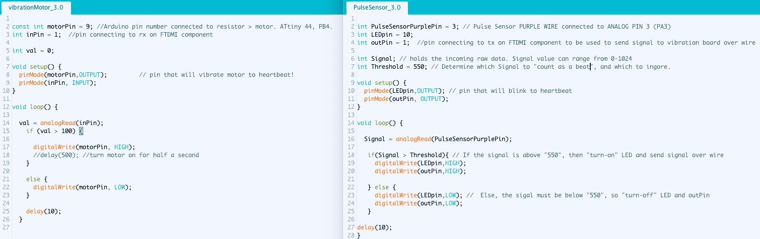
F I N A L P R O J E C T T I M E ! ! !Moving onto Plan B, I began working out the Arduino code for having the boards communicate over serial via wire. Fortunately, HTM(a)A guru Brian interrupted my work flow pointing out how I was overcomplicating things, that rather than working out serial communication, all I needed was one wire that was either “high” or “low”. Meaning, a pin on the sensor board goes high when the pulse is detected and, being connected to the wire, allows the connected pin on the other side (board) to respond by turning the motor on. Simplicity is beauty. Here is Brian’s blackboard lesson for me and my new code which was cut in half after simplifying things.

Having decided to stick with the wired communication, I will use my original sensor board and this new, more compact actuator board.
Here is the final code used to program these boards:
Returning to casting and molding at the end of the semester, I approached the creation of my silicone heart from a more refined perspective. As mentioned, I discovered why it’s crucial to make a “mold for the mold” and not simply a negative mold out of machinable wax. Since we are out of wax blocks in the lab, I made a positive mold for 3D printing. Once done, I will make an oomoo mold from that then cast my silicone heart using this secondary mold.
I used all the techniques learned the first time around in Rhino with the addition of “Offset Srf” to increase the wall thickness. I also discovered how crucial it is to switch Views constantly depending on the needed actions to take. For instance, adding “z” to mesh control points from the Right or Front views is way more accurate than in Perspective. Last time my molds ended up floating in Perspective and it was hard for me to make them planar again. This time I worked in Top view as much as possible in the beginning so that their bases would stay planted.
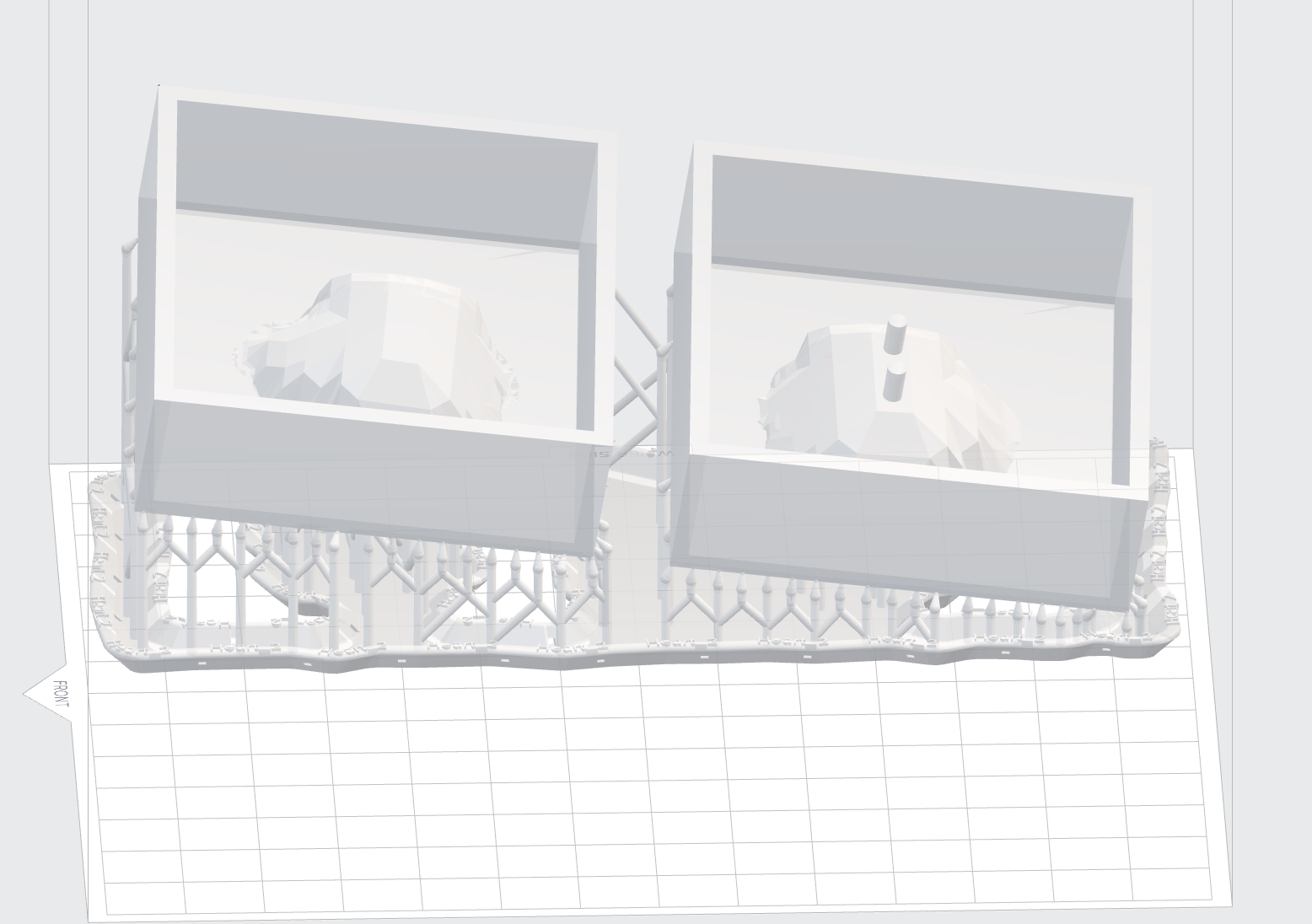
Since the Formlabs was occupied, I used the Sindoh. About 3 hours in, an error occurred. I had sped up the settings too much which caused the base to peel up in one corner. With the sped up settings, the job was going to take thirteen hours. Not wishing to slow down the settings to make the print time even longer, I decided to move forward with the mold I already created.
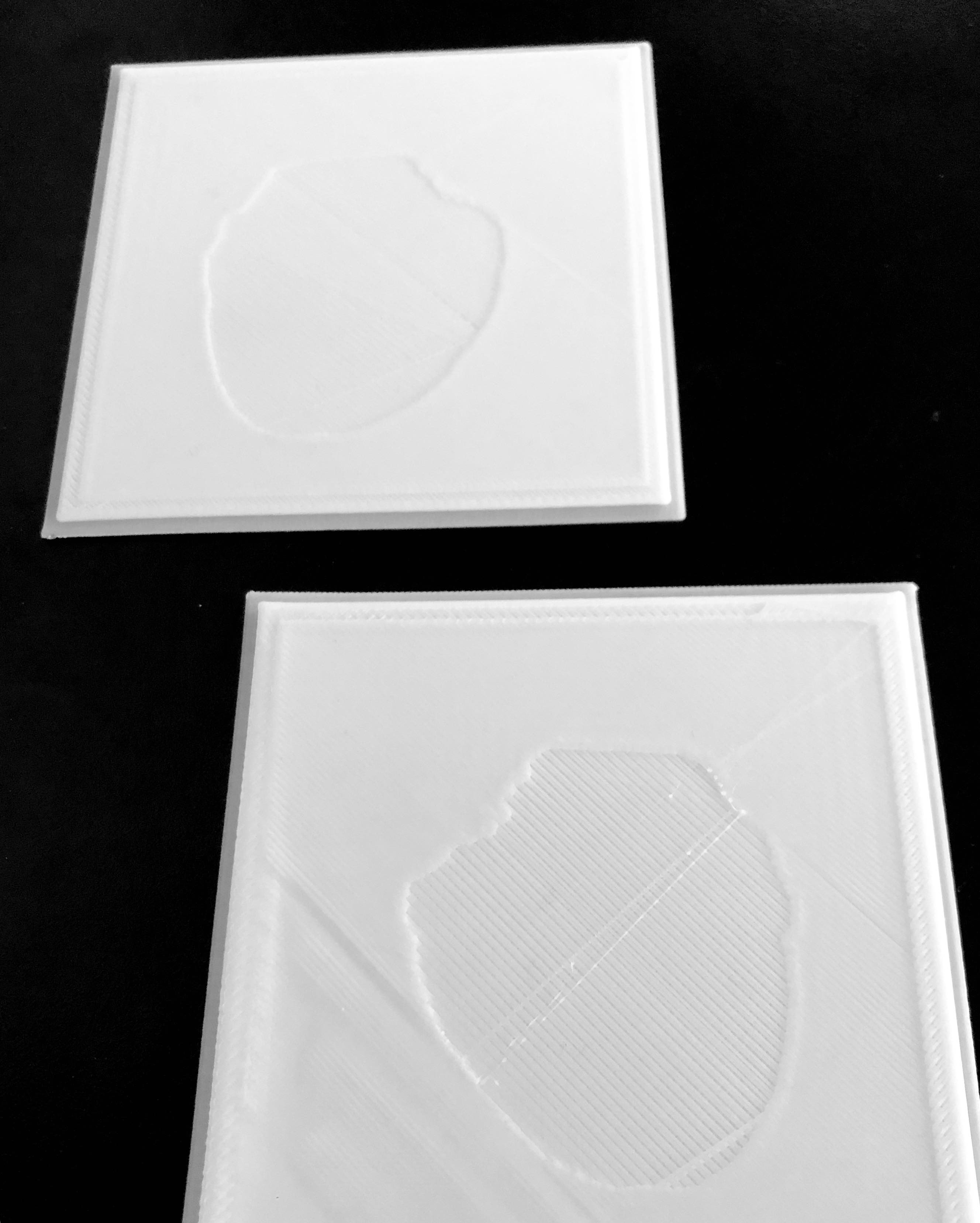
Using the rubber silicone for casting as before, I poured one heart half about half way full then let it cure in the convection toaster oven for twenty minutes at 150 degrees. Then I placed the motor inside and filled in the rest. Once the other heart half was done, the two halves adhered without any glue no problem. I need to continue experimenting with materials though as the silicone cured on the stickier side this time which will make for a strange encounter for the audience member who will soon hold the heart.
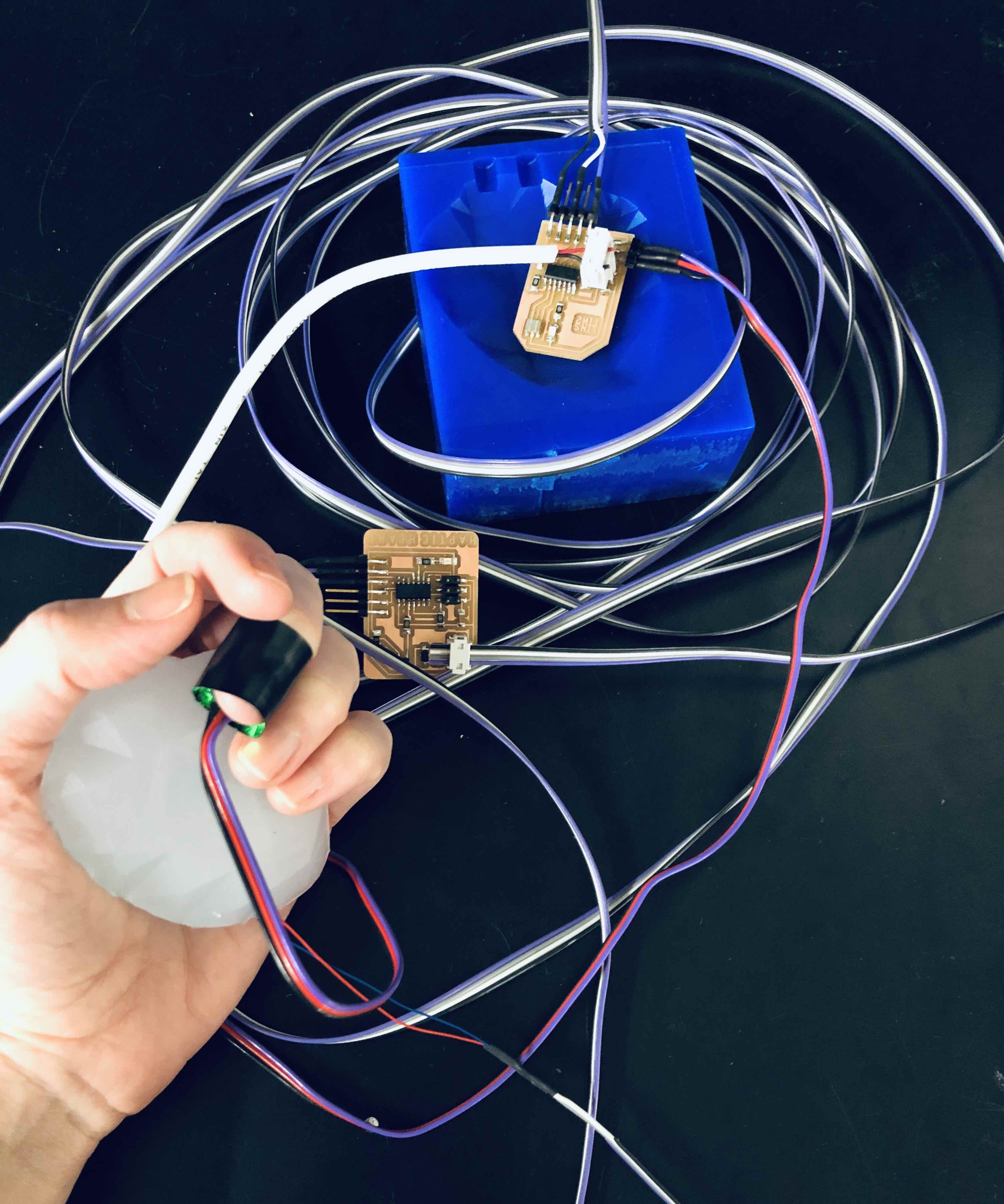
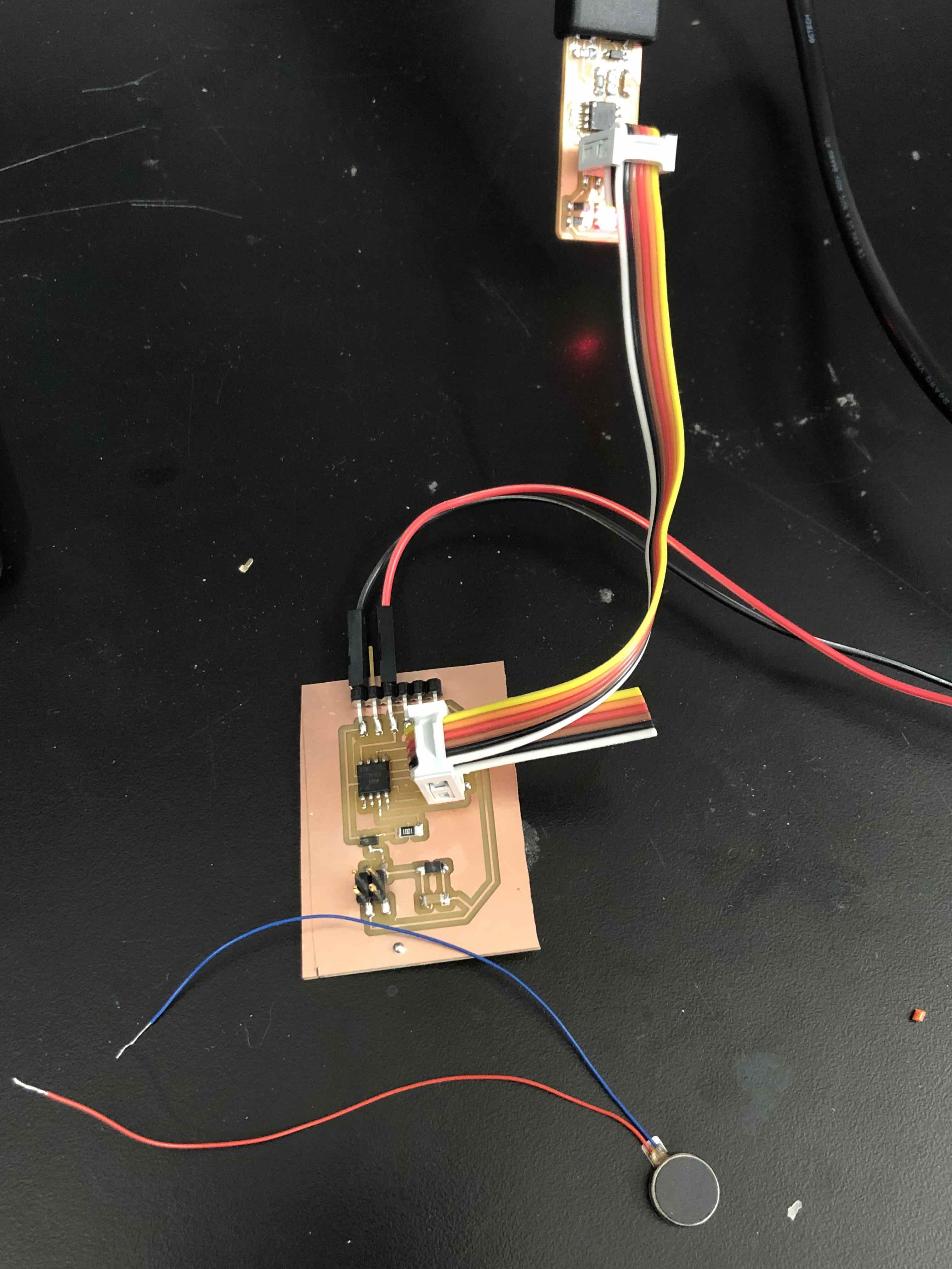
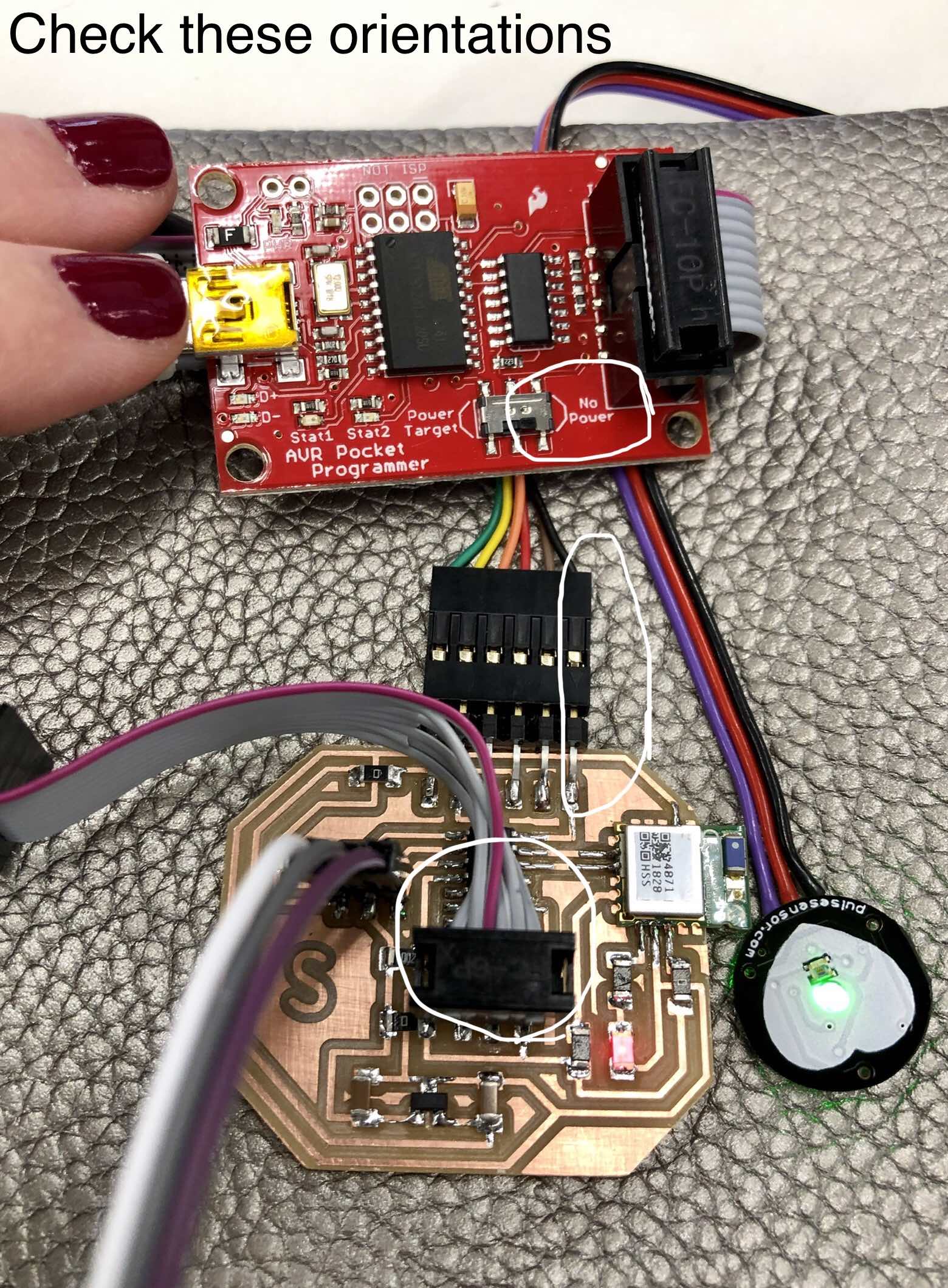
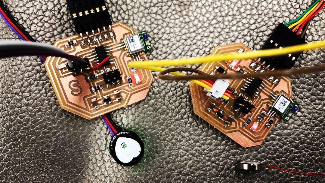
Before permanently linking my two boards together with wire, I tested out this configuration for VCC, GND, and communication:
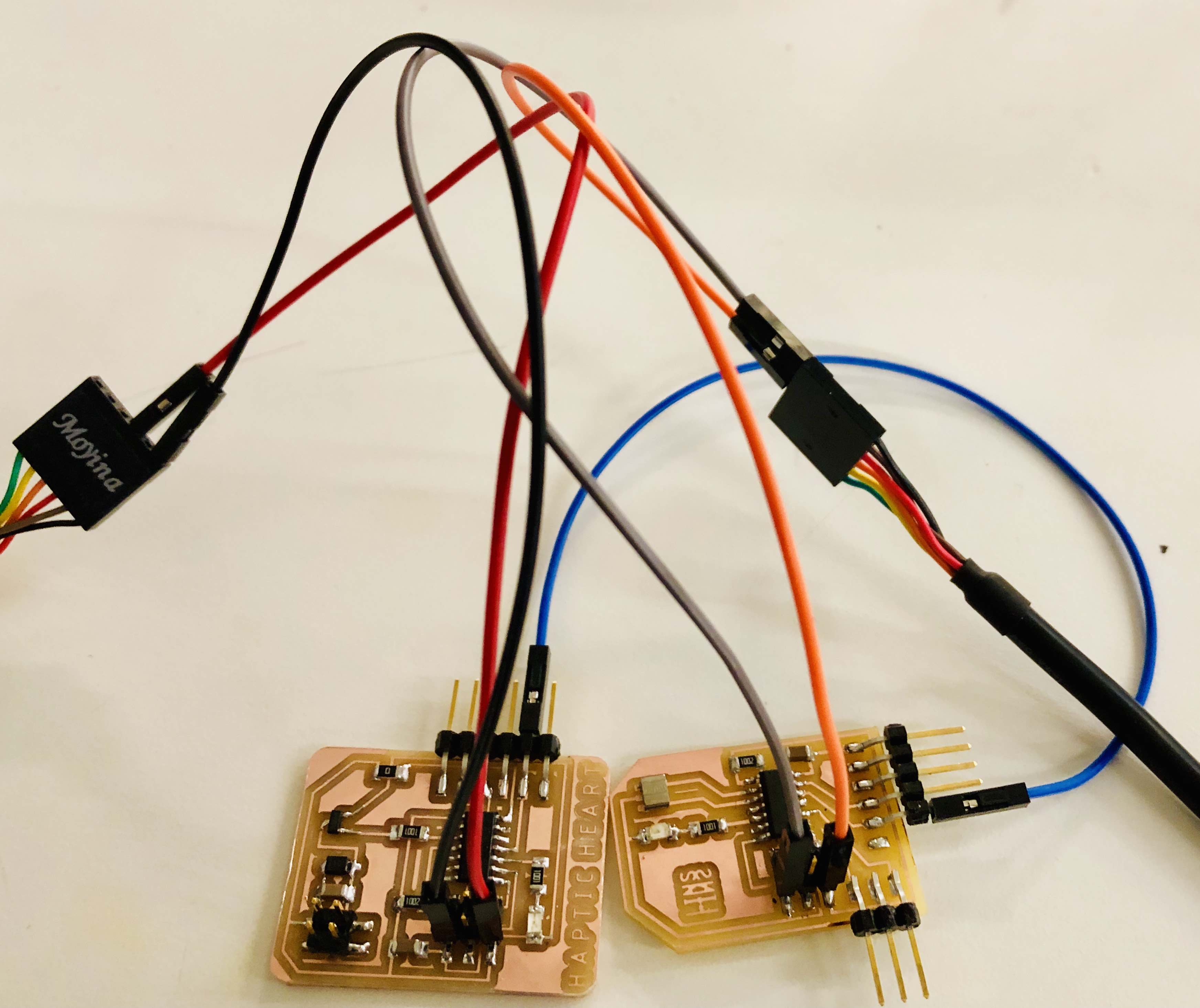
For the next several hours, I spent a lot of time stripping, tinning, soldering, and heat shrinking tubes. By the end, I developed a nice technique:
- Peel wires apart leaving one inch “tails”. Strip just the tips. Do not twist hairs. This makes them fray.
- Hold the led parallel to stripped wire and solder on (tin).
- Cur shrink tube same length as metal pins then “string” on the “tails”.
- Liberally coat metal pins on board.
- Adhere wire to to pins by reheating solder just enough.
- Lower shrink tubes and heat lightly with hot air gun. Too much hot air will melt off the insulation of the wire.
Nothing compares to the utter joy of ending an eighteen hour work day with EVERYTHING working!
Video
And just for Neil since I know how much he appreciates the total integration of all weeks’ lessons, I’ve added to my wire necklace my 3D printed chain which lowers the sensor board perfectly over my heart :-)
(Video) Rehearsing with my heart before our final review...