Electronics2 Week07
how to make (almost) anything
Embedded Electronics
Week 07
This week’s assignment was to read a microcontroller data sheet then to make the microcontroller we designed, milled, and stuffed in week 5 “do something”.
I began this week’s assignment by climbing into the AVR-microcontrollers C programming rabbit hole. By ingesting various How to Make (almost) Anything guru’s tutorial slide decks and getting lost in their hyperlinks, my brain gradually began to put it all together. I am amped about beginning this journey and look forward to supplementing my data sheet reading with Elliot Williams’ book AVR Programming: Learning to Write Software for Hardware which I ordered off Amazon.
I have only begun entering the world of code this fall. At the Harvard Graduate School of Design, I am taking an Introduction to Computational Design: Space with Panagiotis Michalatos. We are primarily working in C# with the goal of designing more effectively in Rhino/Grasshopper. While the C and C# syntax is not the same, structurally, understanding C# has made working in AVR C less intimidating.
What has been most thrilling this week has been thinking about and working with code at the level of bits. Because of this, though I programmed my microcontroller using Arduino’s C-based programming language and then with Neil’s adapted hello.ftdi.44.echo.c program, I enjoyed using Rob’s ultra-raw program the most. While Rob and I agree that in the long term, Neil’s is more elite because of its amenability to editing and expanding, Rob’s was a clearer window into how AVR C works which was more complimentary to what I’ve been reading.
(Impromptu class with Rob Hart)

(Integrating Rob's class material into my own notes and logic)

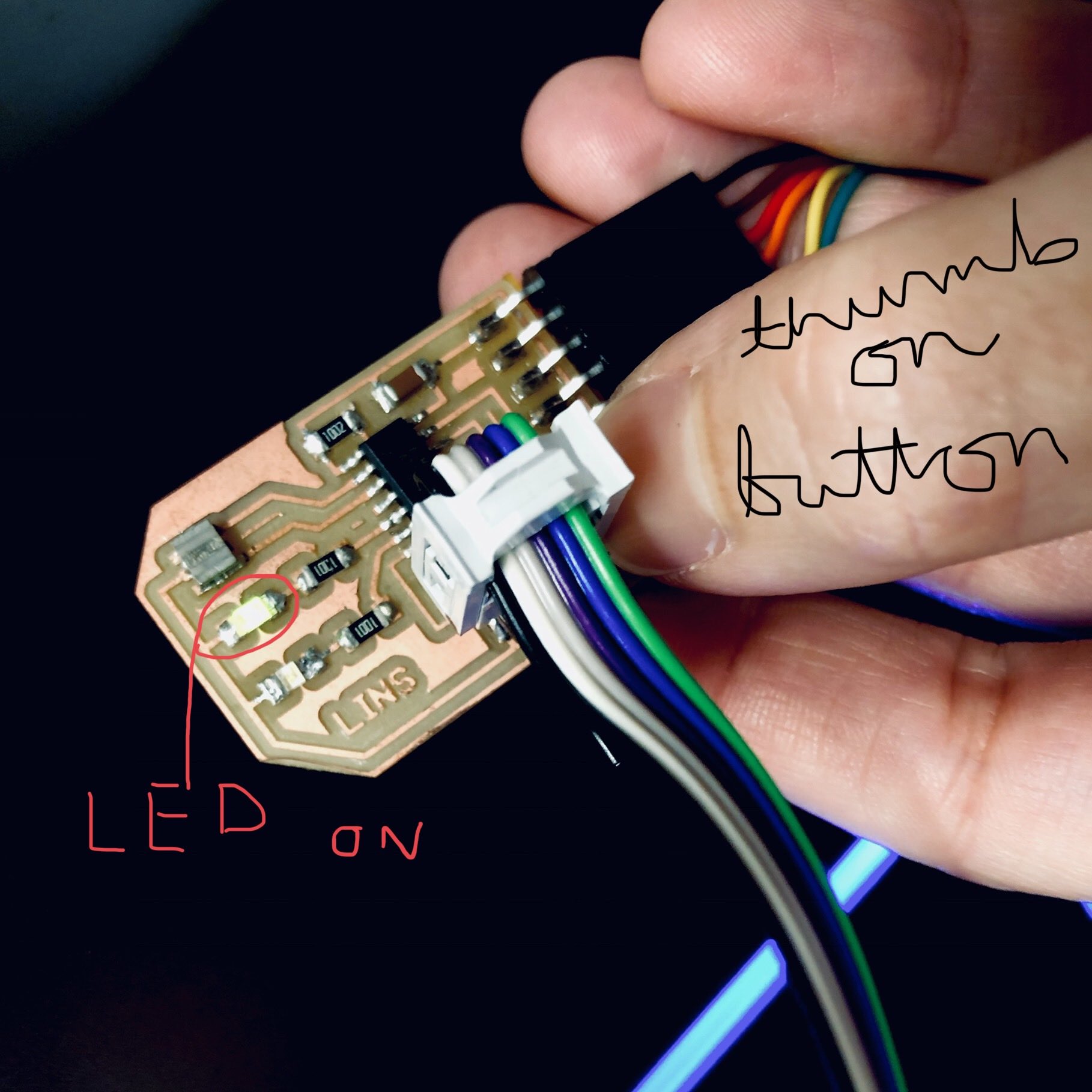
A quick word on using an Arduino program, CHECK THE ARDUINO ASSIGNED PIN NUMBERS. These are different than the pin numbers outlined in the Attiny44 data sheet. For instance, on the data sheet PB2 (where my LED is connected), is associated with pin 5 but in Arduino, it is associated with pin 8. The goal of the Arduino program was the same as Neil’s and Rob’s… when I push the button, the LED lights up and when I lift my finger off the button, the LED turns off. After programming my microcontroller with an Arduino program borrowed from a past year’s student’s site, this simple relationship between light and button was totally erratic. I suspect it could have to do with the lag time resulting from the retrieval of functions in the Arduino library which I’ve heard is an issue.
The following is a deduced summary of what I’ve learned thus far about embedded programming in AVR C.
- Include your libraries up top. For example, #include
lets you refer to the registries in the data sheet using the same labeling. - Declare variables and include mini-functions next. For example, #define [variable name like LED] [port label like PB2] so that you can just write LED in code and program will retrieve data automatically from PB2. This way, is you want to run your program with an LED in a different port location, you only need to indicate its “address” up top and not throughout the entire program.
- Begin to write your program, typically by writing in main(void) { and always complete it with a closed curly bracket, }
Next, I found thinking about the three registries in the below order and writing code that refers to these registries also in the same order helpful…
- DDS (Data Direction Register). Set bits to 0 if you want them to be inputs or 1 for outputs. A mnemonic trick I came up with is a 0 is like a ⭕️ where data can enter through and 1 is like a ☝️that points data in a specific direction.
- SPORT. Even though you set the direction in the DDS, you must decide, more or less, if each pin is “on” or “off” by setting the bits to 0 or 1. If you assign a pin with DDS 0 a 1 in the PORT registry, you are setting its internal pull-up resistor. Mnemonically, I imagined the pin as a person “pulling up” 5 volts into their arms then waiting for the right moment to use their gathered energy. Otherwise, the input pin has zero volts. If you assign a pin with a DDS 1 a 0 or 1, it’s more straightforward. If “high” (1), it is “on” or has 5 V and if “low” (0), it is “off” or has 0 V. Of course, my understanding is so elementary that I’m sure I’m probably oversimplifying this.
- PIN. I am most foggy on what the PIN registry does but from what I gather, you go into the PIN registry to “read” what’s been “written” in the PORT registry. This is helpful when you need to use a bit-mask formula to assess a boolean expression. By using PIN and not PORT, your bit-mask operation won’t change the value of the bits but rather, just use them to determine whether the result is true or false.
This is hard to articulate, but essentially the DDSx, PORTx, and PINx are all looking at the same 8 bit indices of x but each registry is relating to the x indices differently. So, DDSA = 0b00000010 and PORTA = 0b00000010 and PINA = 0b00000010, says “PA1 (Port A-1) has an output direction, is spitting out 5 volts, and is turned on”. Do you see what I mean by the same index now, in this case all for the 1 index in Port A? Also, as an example, 0b00000100 can be written as (1 << 2) or (1< For more on bit-mask operations and registers, check out this crystal clear article: http://home.roboticlab.eu/en/avr/registers Here is the program written by Rob that I adapted for my microcontroller. Unlike the board’s run with the Arduino based program, it worked very consistently. You can use the Arduino IDE for straight-up AVR C, but keep in mind, that if you do, use these settings accessed from the Arduino Tools dropdown menu: