Inputdevices Week09
how to make (almost) anything
Input Devices
Week 09
This week’s assignment is to “add a sensor to a microcontroller board that you have designed and read it”.
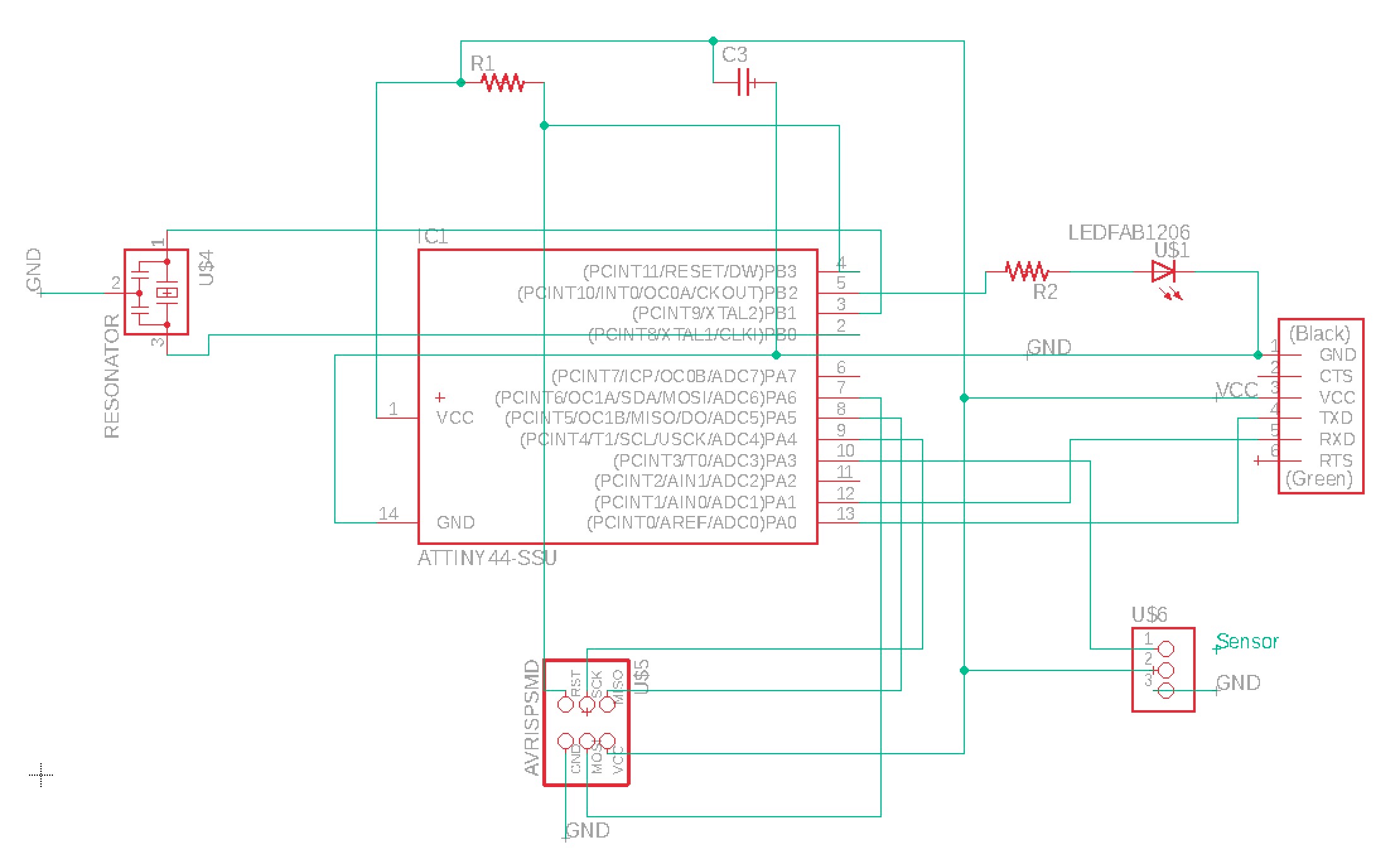
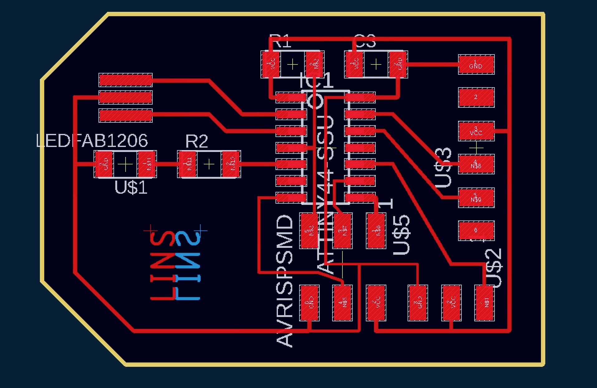
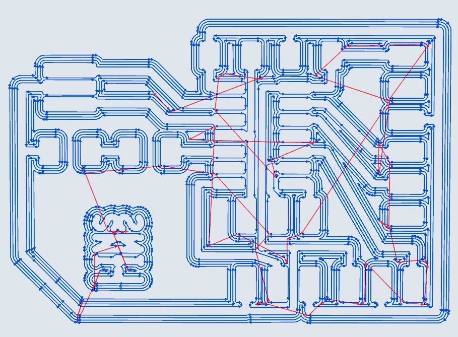
For Input Devices week, I am motivated to work with a heart rate sensor. As references, I have found past How to Make (almost) Anything Student student Oscar Rosello’s site and Github documents from the PulseSensor I purchased to be extremely helpful. The first step was to design a new PCB. As a starting point, I adapted my PCB design from Week 05, removing the button as well as an LED and resistor pair and adding a three-prong component for connecting the PulseSensor to. I was mindful to make sure the three-prong component was placed relative to VCC, GND, and PA3, an analogue to digital (ADC) pin.
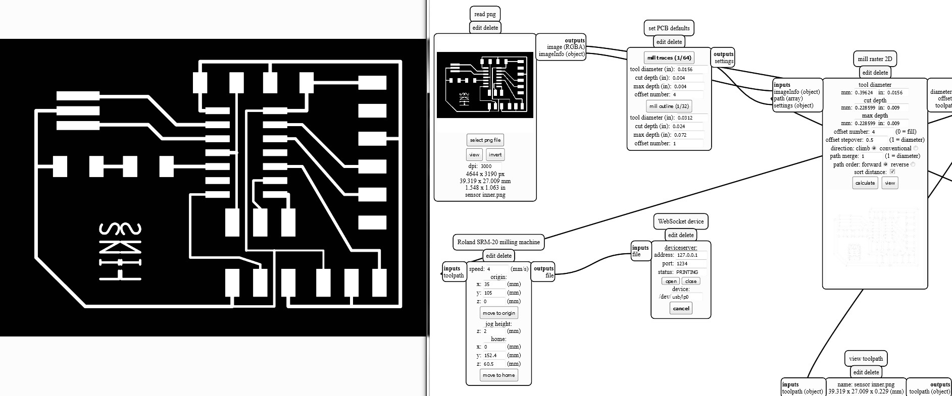
This is the third assignment requiring work on the SR20 mill and with each one, the setup and running of the mill becomes easier. The mods software provided by our professor Neil Gershenfeld makes all the difference as it has automatic settings for the spindle speed, feed rate, cut depths, etc. Plus, it generates the tool-paths for our imported designs. To account for Mac’s glitch when exporting images from Eagle, I doubled the DPI to 3,000 and also increased the cut depth to .009 when milling with the 1/64 inch bit.
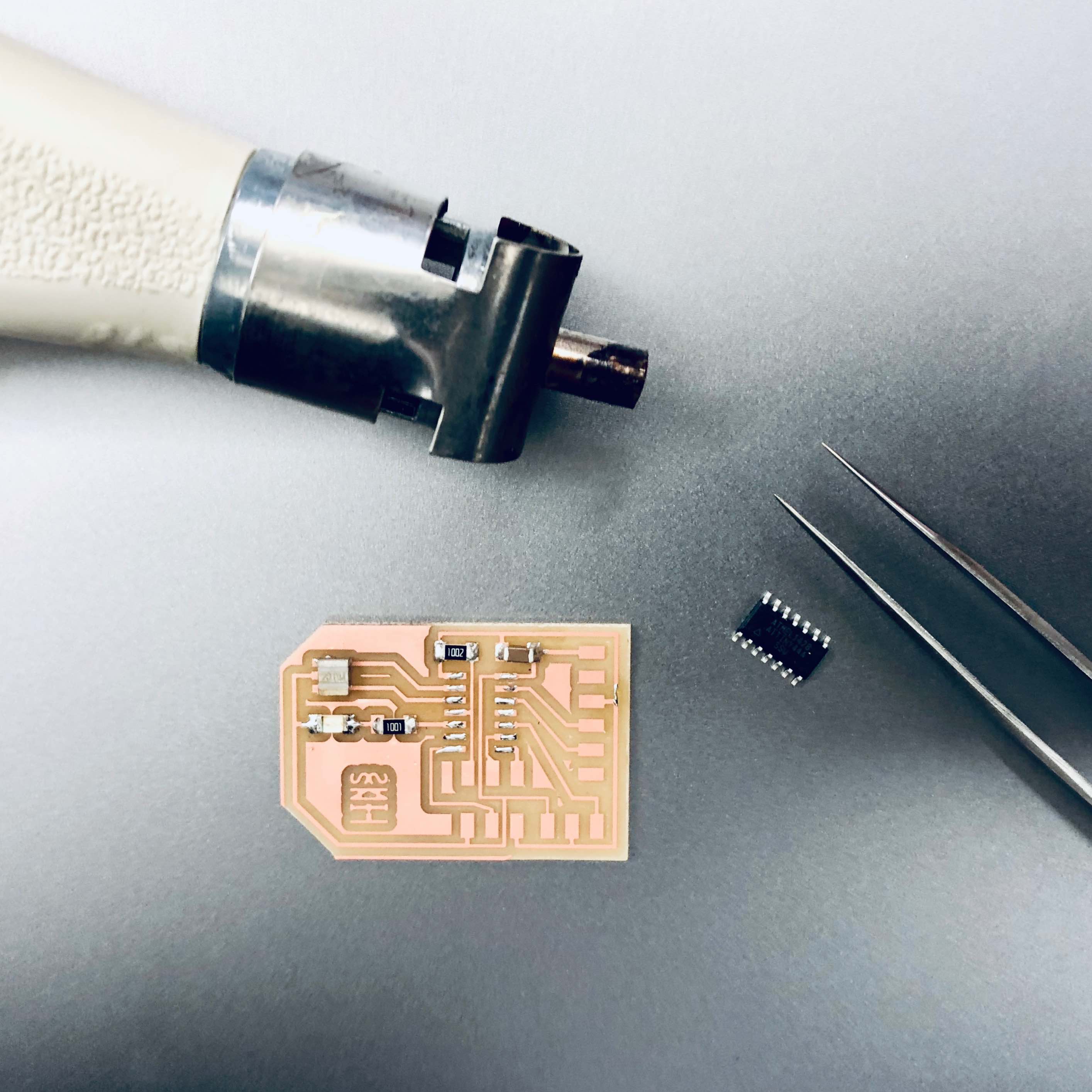
For the soldering, I continued experimenting with the reflow technique of dabbing solder onto the copper pads then reheating it with the air gun before placing the components down with tweezers. I was a bit conservative though in the reheating process as I was concerned about frying my components with the air gun. This caused my ATTiny to barely adhere to the mounds of solder which should have been more like puddles of liquid metal. After discovering the board did not work properly and a lot of trouble shooting with Rob, our Section leader, we made this realization. On a positive note, through the trouble shooting process, I learned a lot about how to use the Meterman, best connect my PCB to the computer, fine tune the settings in Arduino, and translate the appropriate ATTiny 44 pin number from the Datasheet to the Arduino specific pin number.
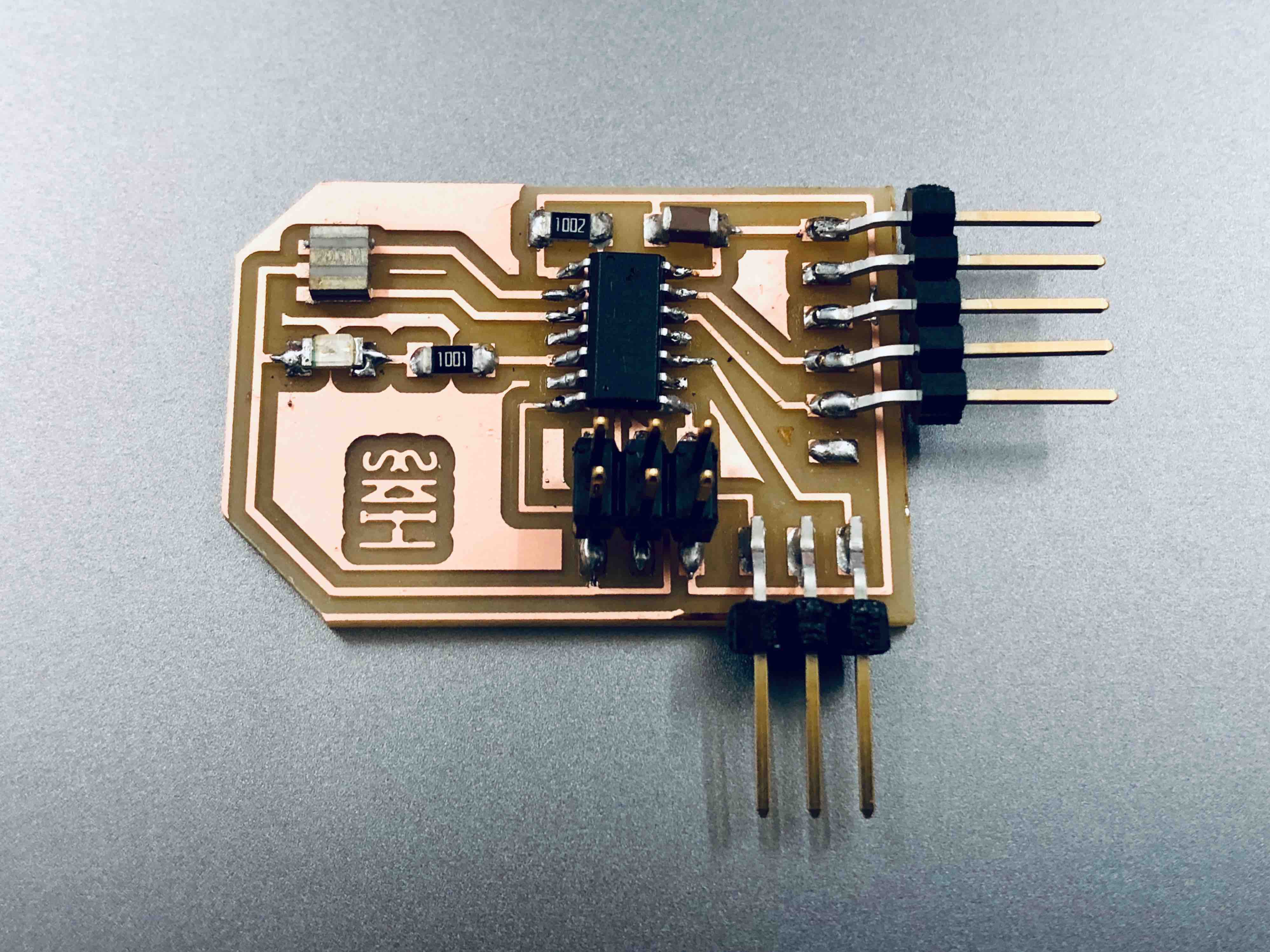
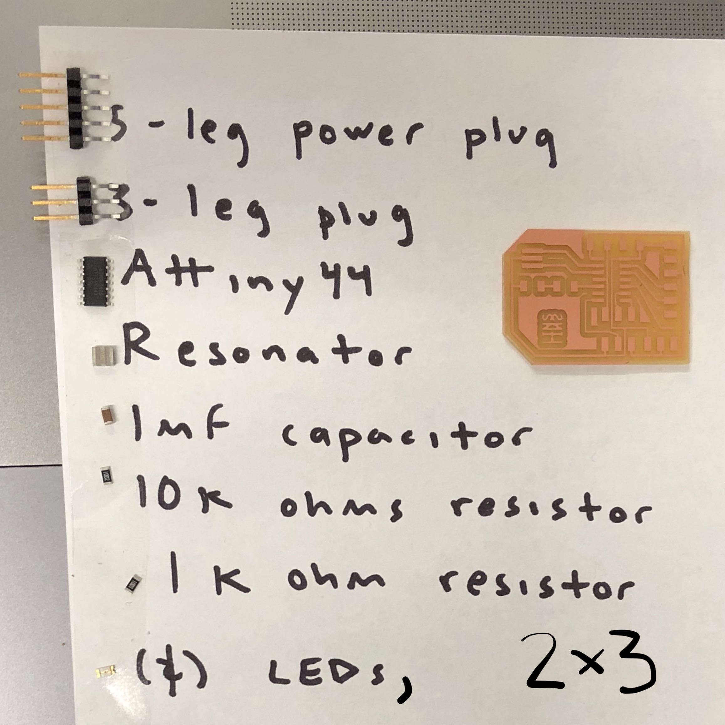
Here are the components that went onto the sensor board:
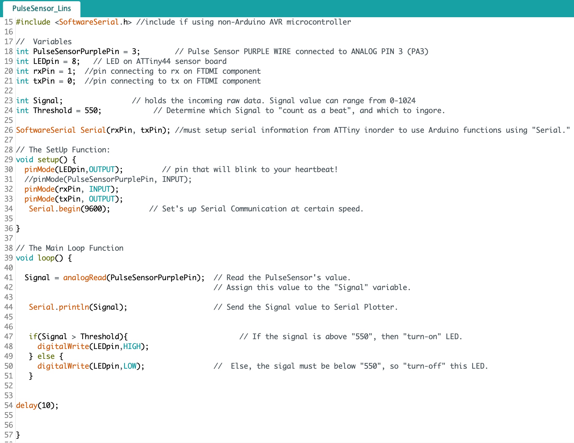
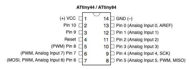
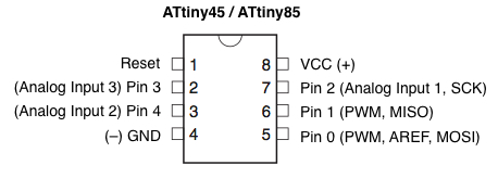
The PulseSensor I purchased from SparkFun came with some starter Arduino code. The real challenge was to figure out how to use code written for an Arduino board on a self-made AVR board. After using two incorrect diagrams, I recalled the one in the High Low Tech tutorial which worked beautifully. Be watchful to read your schematic and board view accurately before looking at the diagrams below to figure out the corresponding Arduino pin numbers.
Translation of ATTiny pin numbers from the Datasheet to the Arduino specific pin numbers:
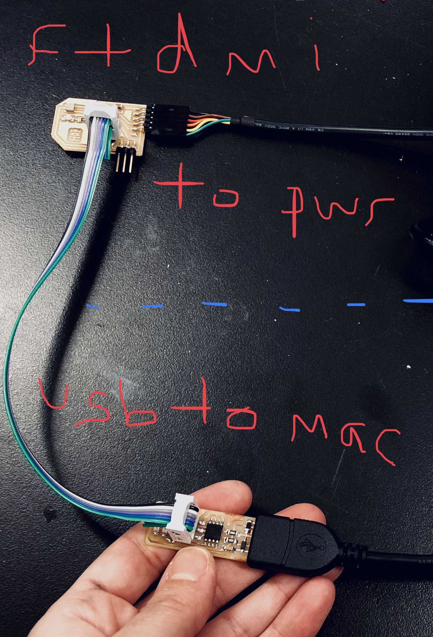
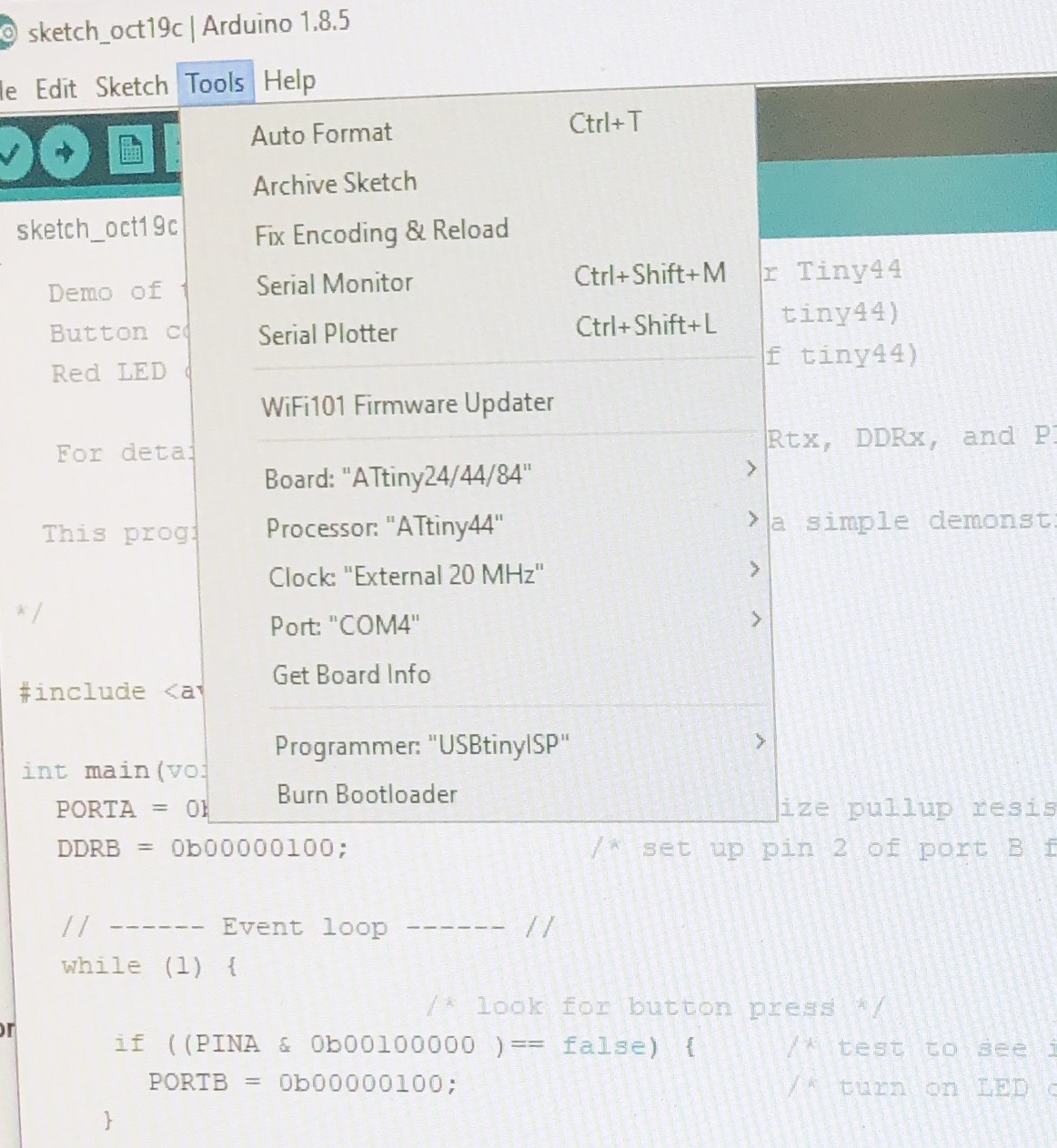
The next coding challenge was figuring out how to setup the serial information needed so that my sensor board could communicate through the FTDMI cable bi-directionally with my computer. In the photo of code below, read the //comments for more details: