Outputdevices Week10
how to make (almost) anything
Output Devices
Week 10
This week’s assignment is to add an actuator to a microcontroller board that you have designed and write a program to make it responsive.
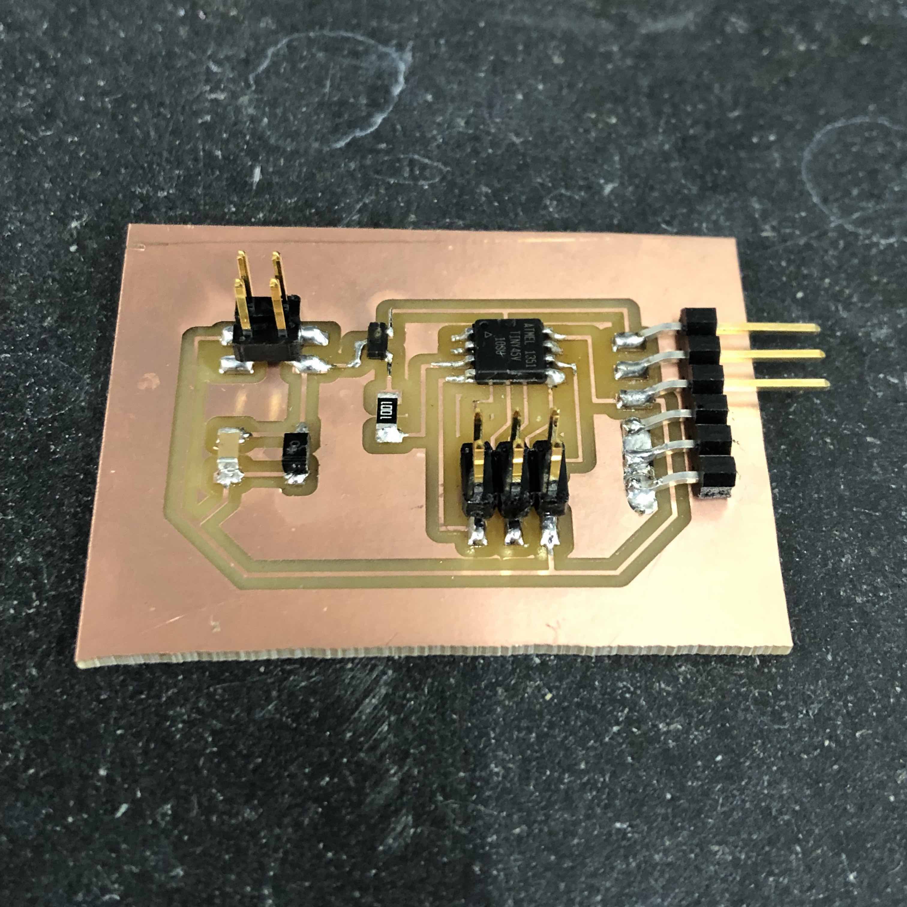
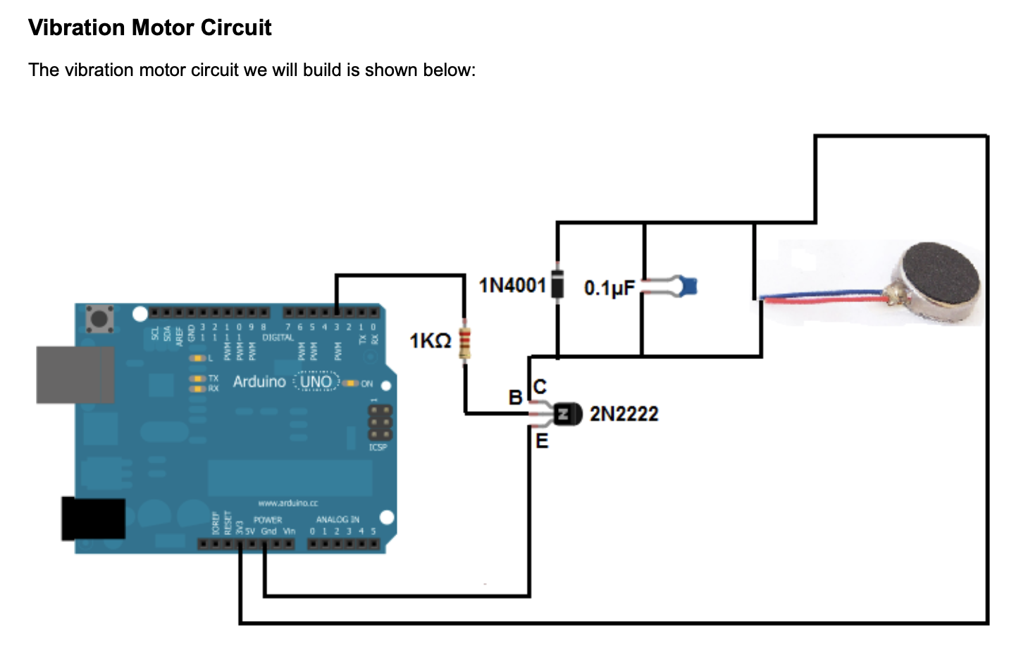
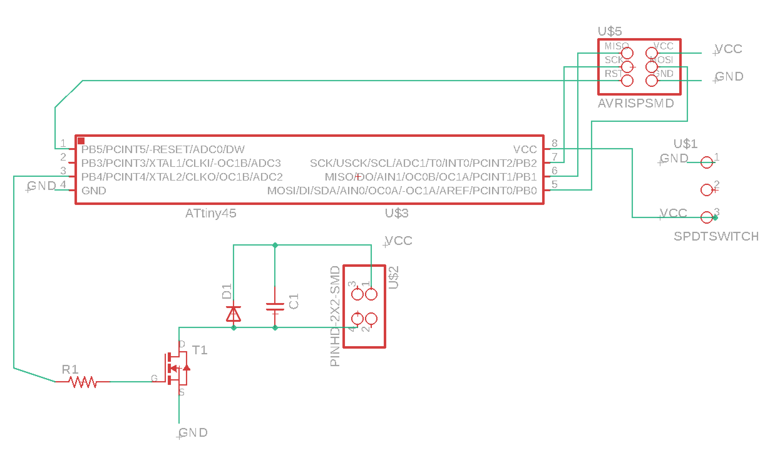
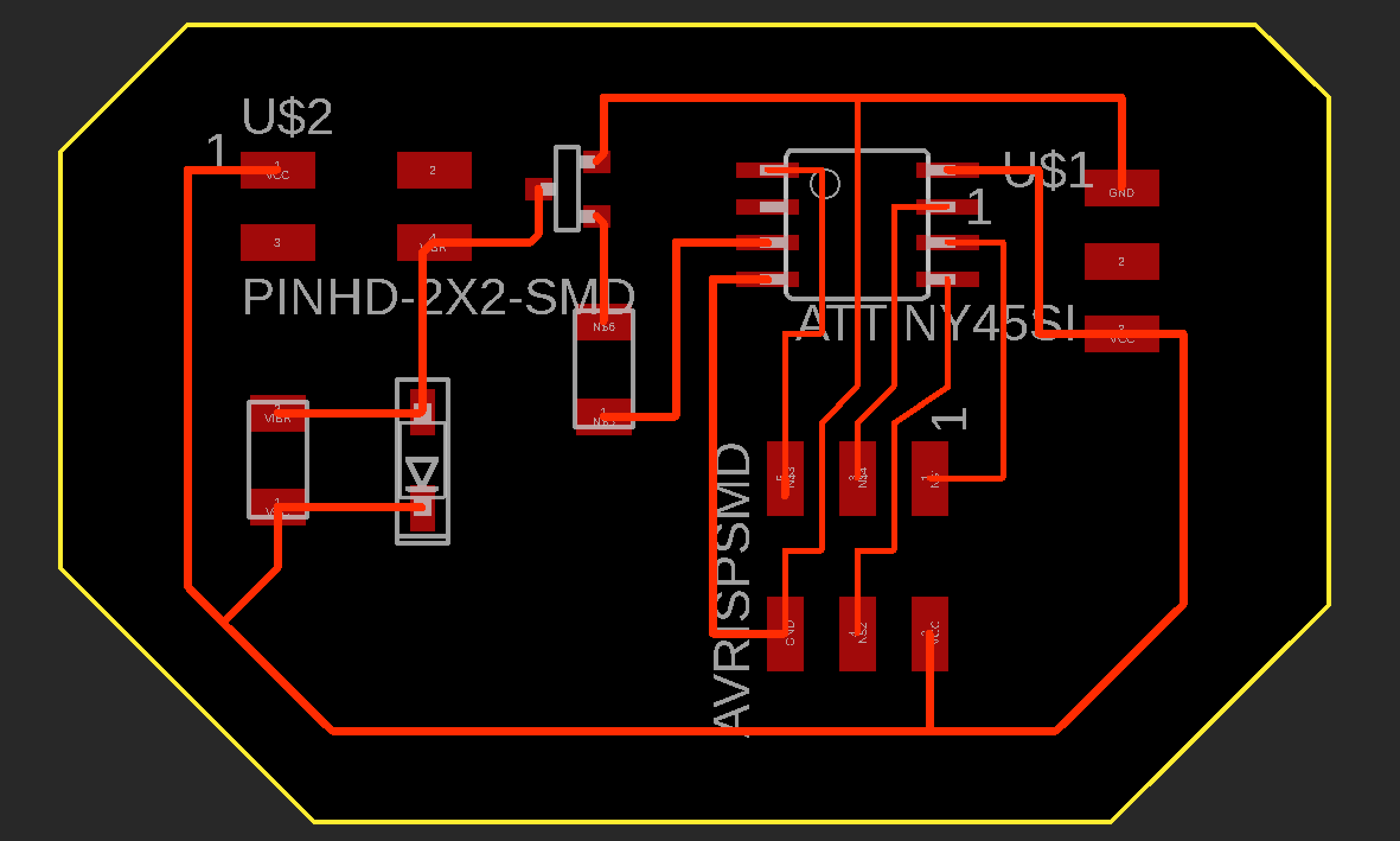
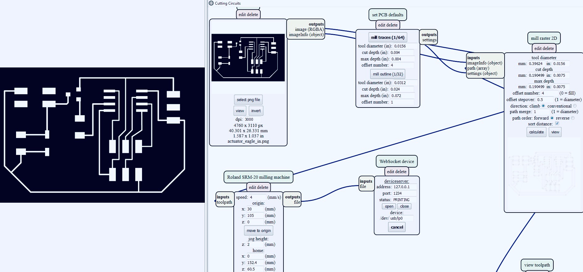
Building on my final project concept of making an abstract haptic heart that vibrates in accordance to my actual heart rate, I decided to design an actuator PCB for programming a mini vibration motor. I ordered a pack of motors from Amazon and found a useful tutorial online titled “How to Build a Vibration Motor Circuit.” The best part about the tutorial was its list of components and schematic for connecting them to an Arduino board which I was able to reinterpret into my own design. Not working with an Arduino, I added to the list an ATtiny 45 as the microcontroller, a 2x3 header pin for programming, a 2x2 header pin for connecting the motor, and an FTDMI connector for power. With Rob’s assistance, if I wasn’t able to find the exact component in the shop, I found an equivalent one to work with. As before, I used Eagle for the PCB design and the SR20 mill in the Harvard Science Center for machining it. Having gone into some detail last week regarding a similar design, fabrication, and coding process, I will be more brief this week. Please refer to the Input Devices Week for more nuanced information like cutting depths and Arduino pin number translation.
Below are screen shots from the “How to Build a Vibration Motor Circuit” tutorial (http://www.learningaboutelectronics.com/Articles/Vibration-motor-circuit.php):
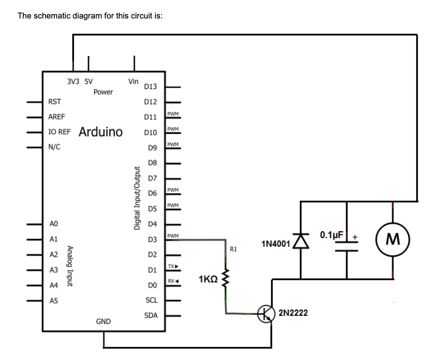
The list of parts I used:
- 1K ohm resistor
- 0.1uF ceramic capacitor
- diode schottky 1A 100v
- mosfet 30v 1.7A
- ATtiny 45
- 2 x 3 header pin
- 2 x 2 header pin
- FTDMI connector
Two things went wrong in the design and soldering process. The first being, I had the rotation of the mosfet incorrect and second, the FTDMI connector, once soldered, broke off, taking with it the copper pads and traces it was attached to. While I was able to manually rotate the mosfet during the soldering phase, I could not salvage the FTDMI connector mess. My attempts to add wire where the copper traces had broke off, failed.
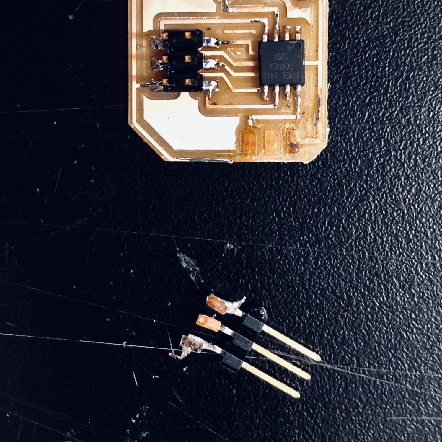
To prevent the above from happening again, I corrected the mosfet orientation and connections in my Eagle schematic and added more distance between the traces and outer boarder. This way the FTDMI connector had more padding to rest on and the traces couldn’t be so easily peeled up. Regarding the mosfet, keep in mind that the Drain goes to the motor, the Gate to the microcontroller, which in my case was via a resistor, and the Source to ground.
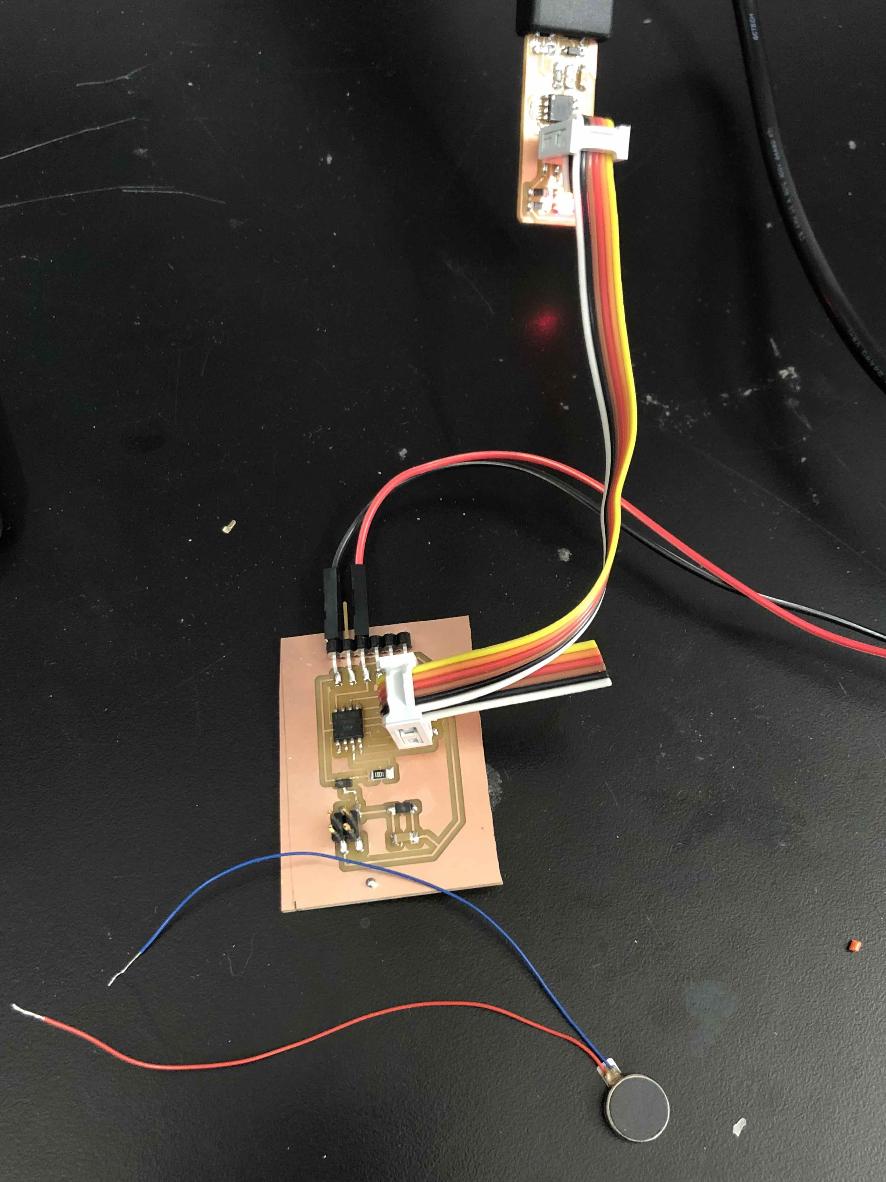
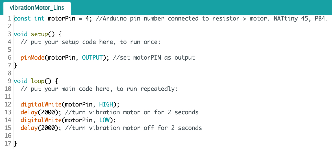
Prior to when the FTDMI connector broke off, I was able to briefly test the vibration motor by touching its two wires to the appropriate soldered pads on my board, at which time, the motor vibrated instantly. Though my new board came out better, so I thought, the motor did not respond in the same way. Programming it didn’t help either. Unfortunately, I will have to return to this next week to figure out why. To be continued…
Further updates on this actuator board can be found on my Final Project page.