Networking Week13
how to make (almost) anything
Networking and Communication
Week 13
This week’s assignment is to design, build, and connect wired or wireless node(s) with network or bus addresses.
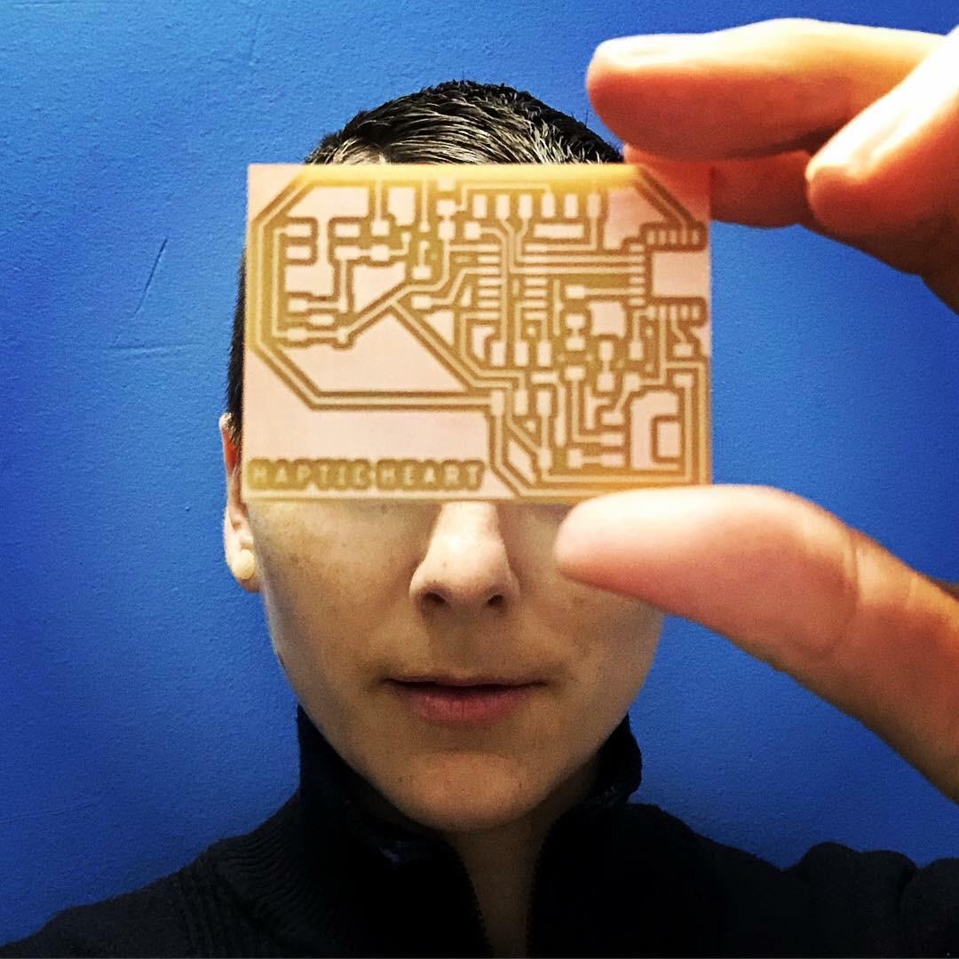
I began this week’s assignment with great ambition, seeing it as an opportunity to make great progress on my final project. For my Haptic Heart project, I will need to connect wirelessly my heart sensor board and mini vibration board so that as I dance, my heart beat will be felt via a matched vibration in the silicone heart held by an audience member. Since I was never able to get my mini vibration board working, I thought I should begin with a redesign of this board to check for errors and to make the addition of a BLE module. I selected the RN4871 module.
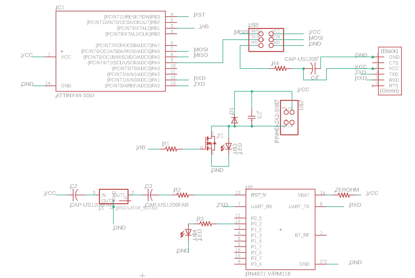
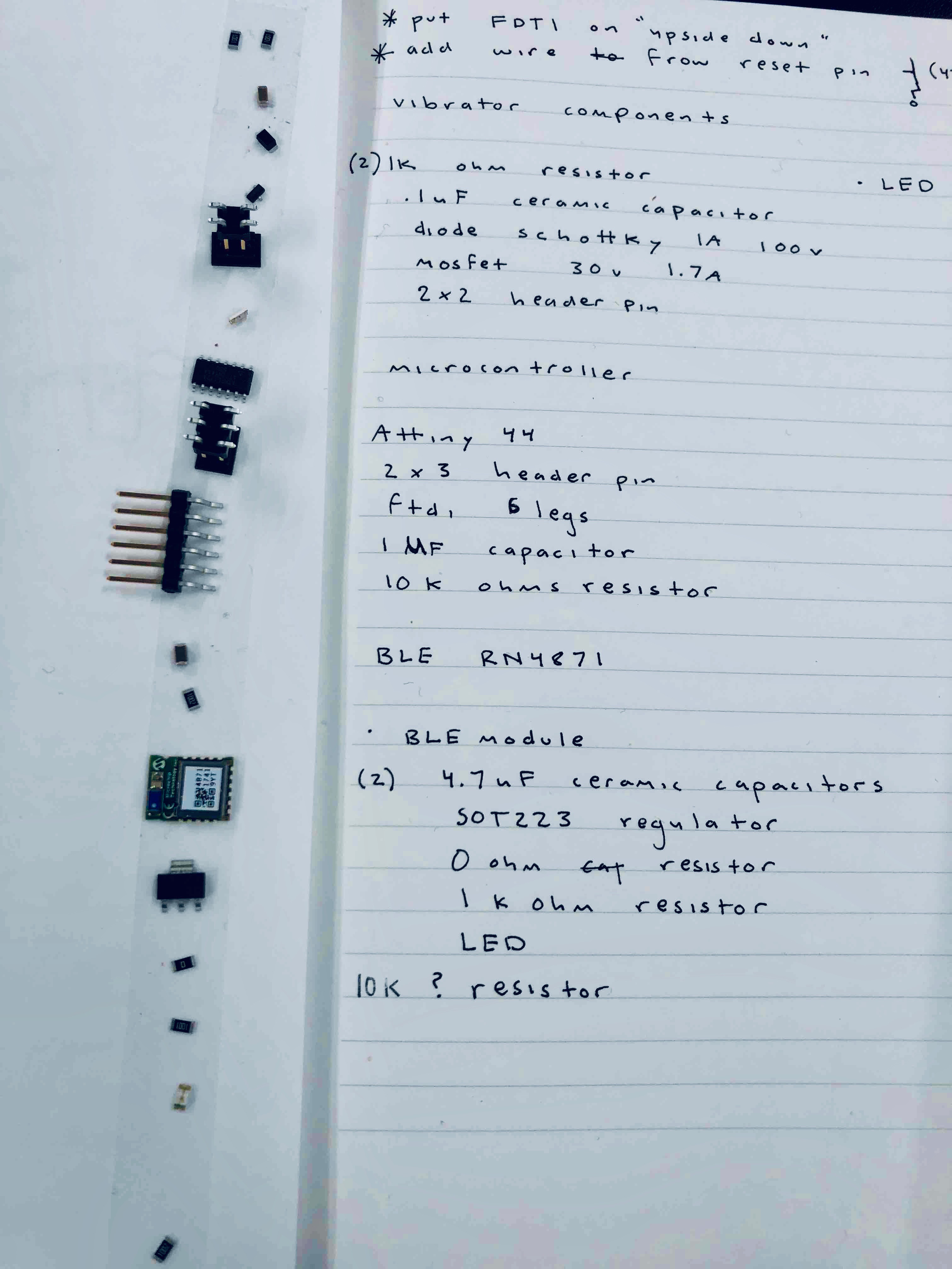
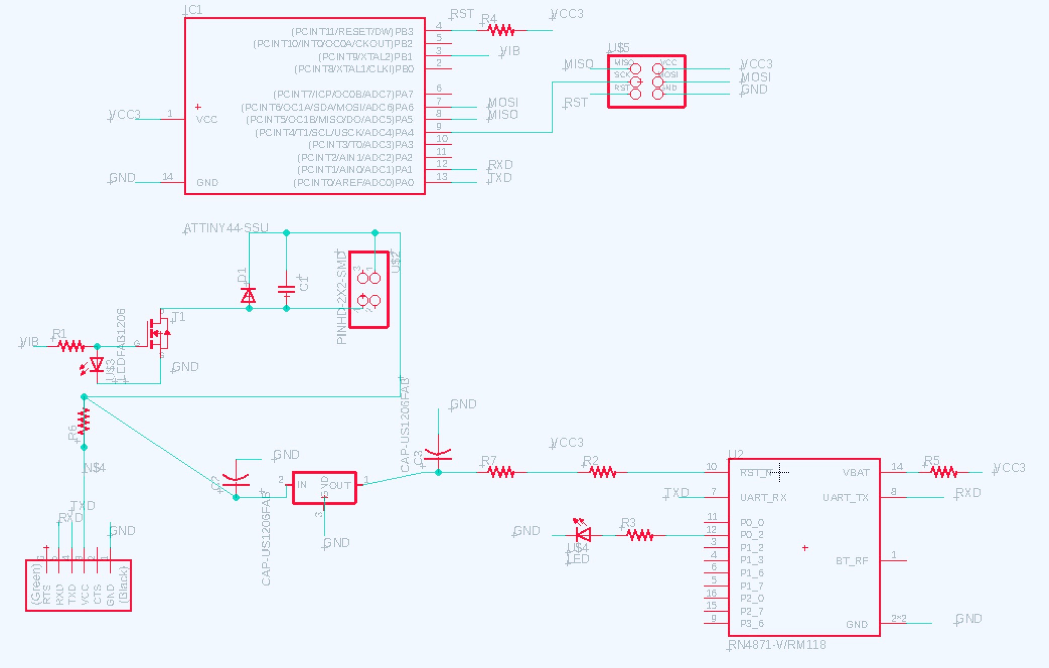
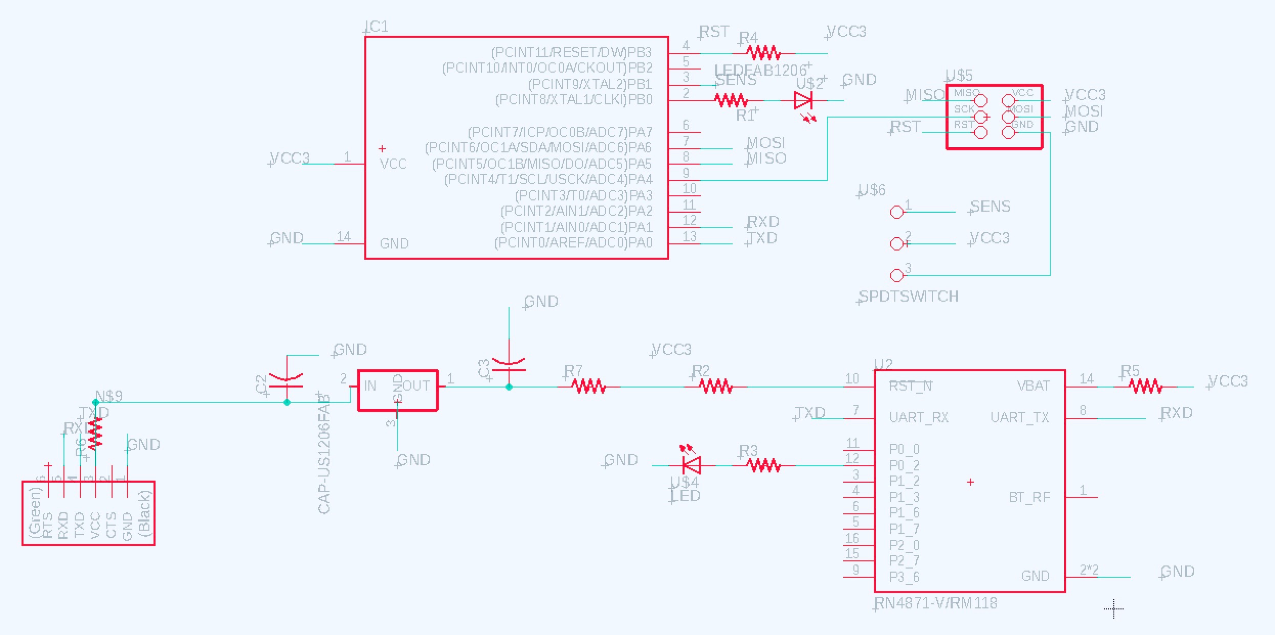
I began by replacing the ATtiny 45 with an ATtiny44 since my first version lacked enough pins to setup serial communication via the FTDI connector, a must for configuring the RN4871. Midway through the design, I noticed I did not have a capacitor or resistor connected to the FTDI VCC pin on my previous schematic nor the reset pin on the 2x3 header connected to the reset pin on the ATtiny. Perhaps this is why my last board did not program! It was quite a challenge to include the sequence on components necessary to support the ATtiny44’s programming and serial communication, the vibration motor, and the BLE module. Sorting through the rat’s nest when switching from the schematic to board view in Eagle is always a puzzle. That said, I made a few decisions I question…
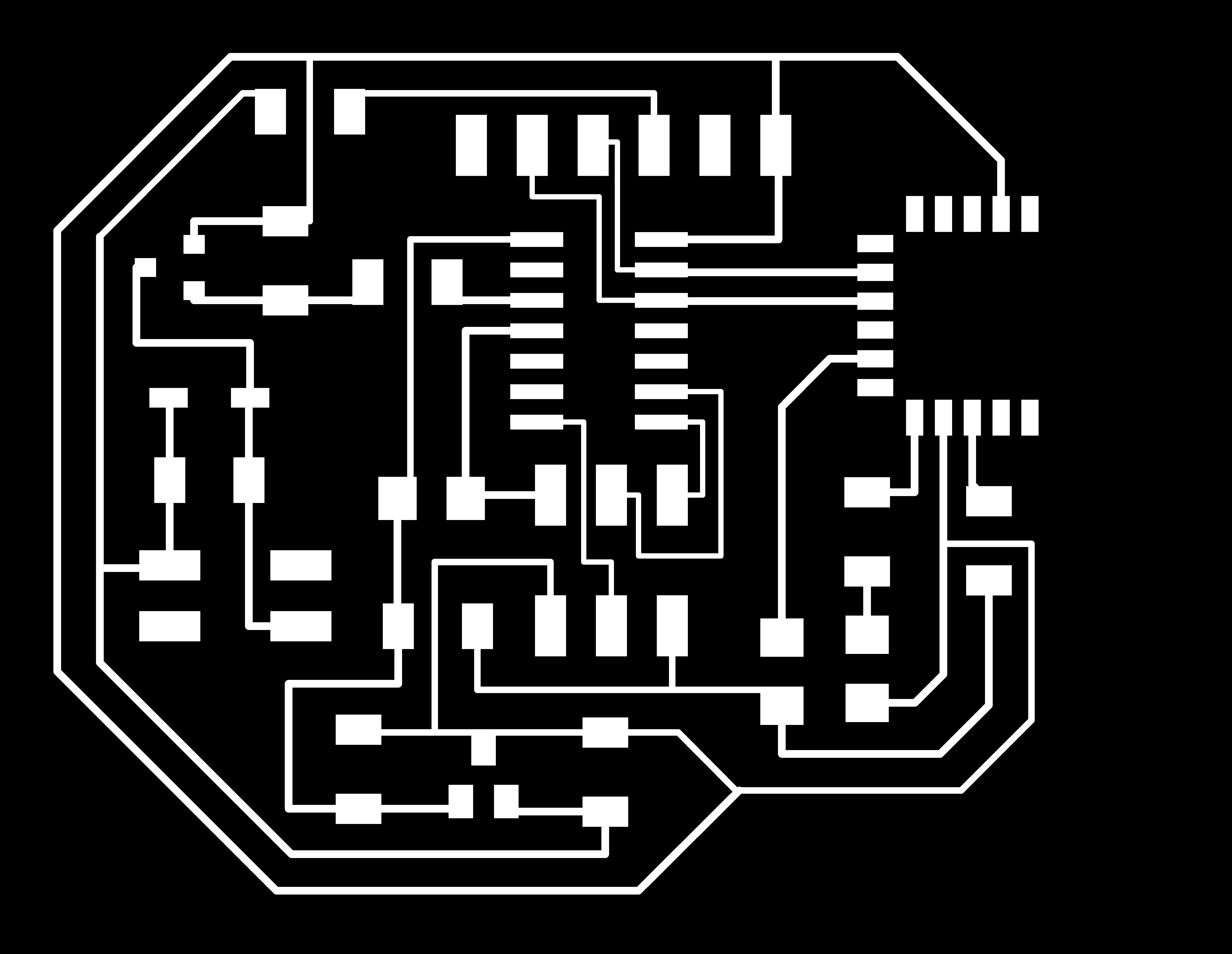
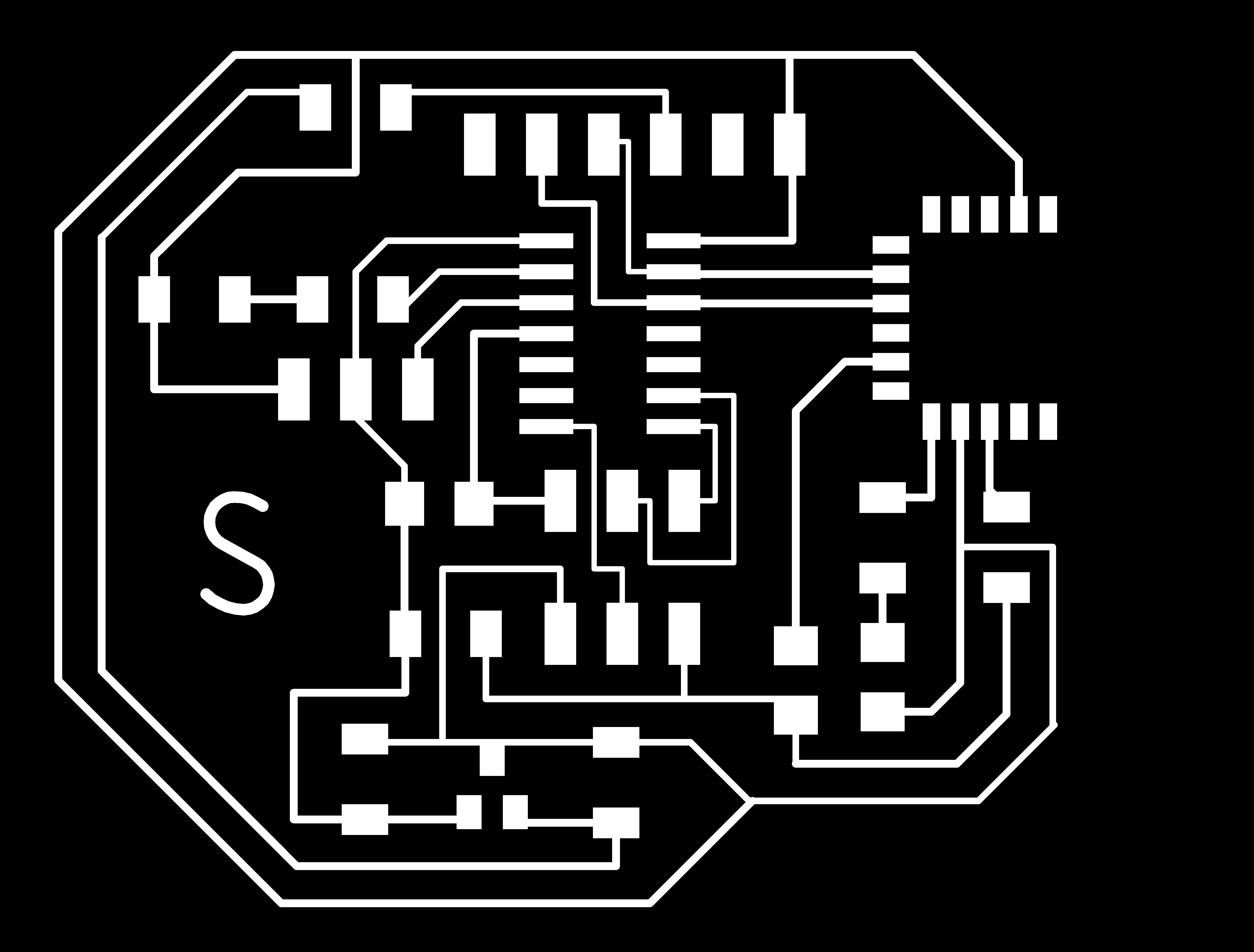
I ran a VCC trace under a resistor. I added a zero ohm resistor along the VCC trace in a different area to allow GND to pass underneath. I added the SOT223 regulator just before the BLE module (including capacitors) instead of right after VCC enters the board from the FTDI connector. I have to plug in the FTDI cable “upside down” since GND is “south” instead of “north” in comparison with previous boards (not sure if the FTDI cable is happy with this).
Following Rob’s advice, I only soldered on the components relating to the BLE so I could test and debug this part of my board independently. Using Cool Term, an app for Mac that facilitates serial communication with BLE modules, I was able to put my module in Command Mode by entering $$$ in the terminal. But within minutes, the LED on my board went extremely dim and then I lost communication all together.
Of my concerns, the one that was an issue was the placement of the regulator, which in fact does need to be placed in immediate proximity to the FTDI VCC pin. This is because the ATtiny also needs to be running off 3.3 volts so that it’s RX and TX connections to the BLE are operating at the same voltage. Also, I made an amateur mistake and forgot to ground several capacitors on my board.
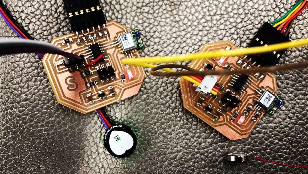
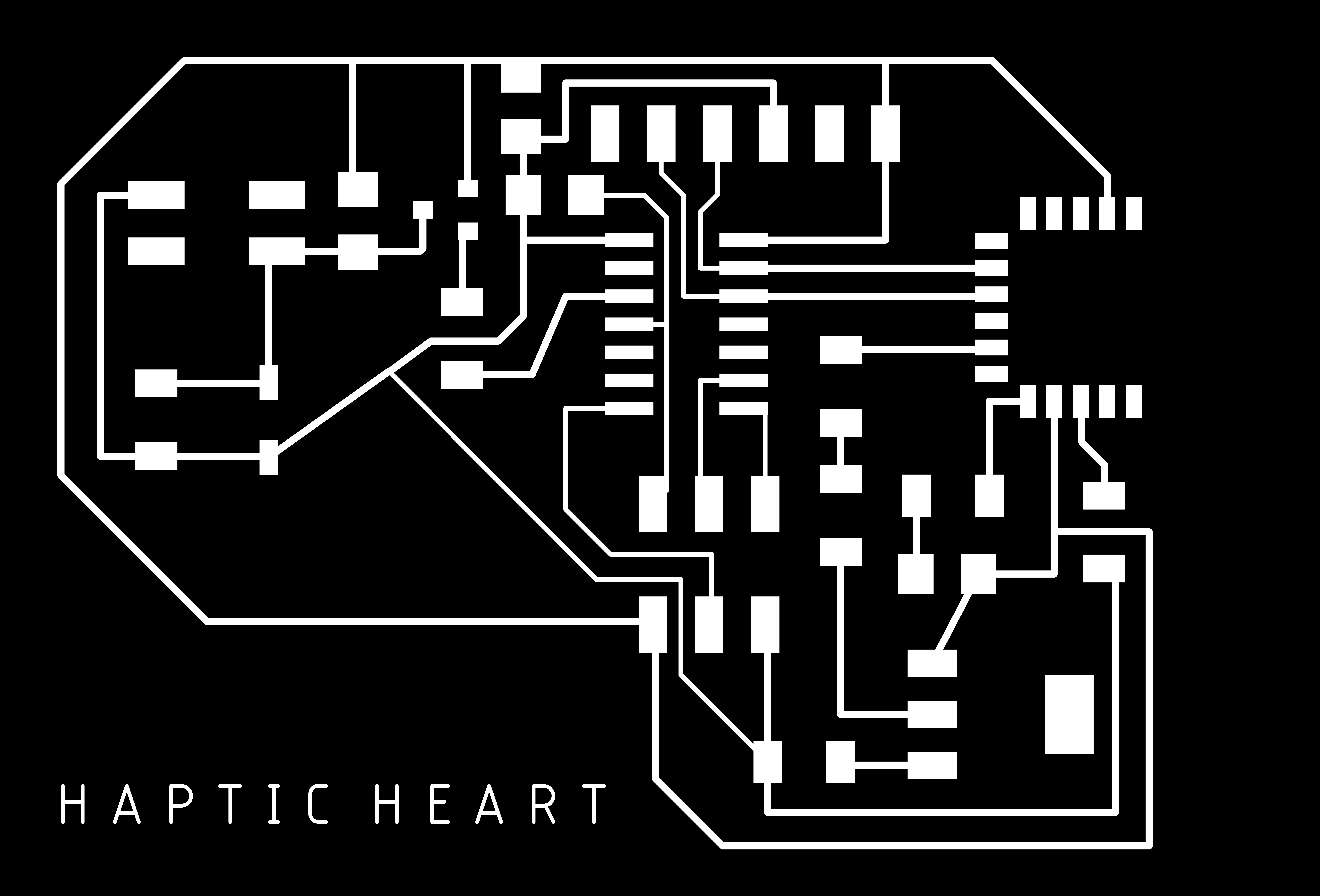
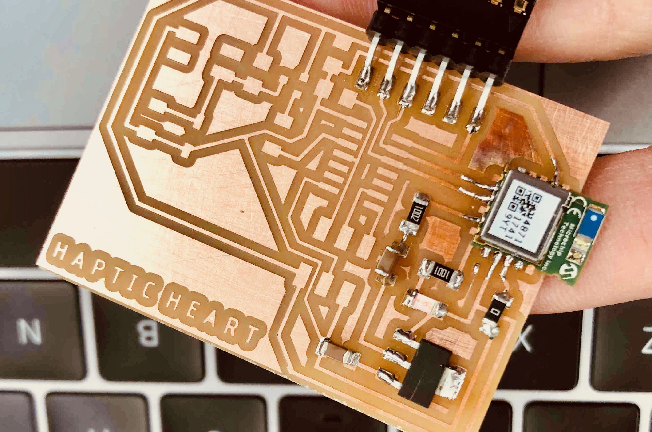
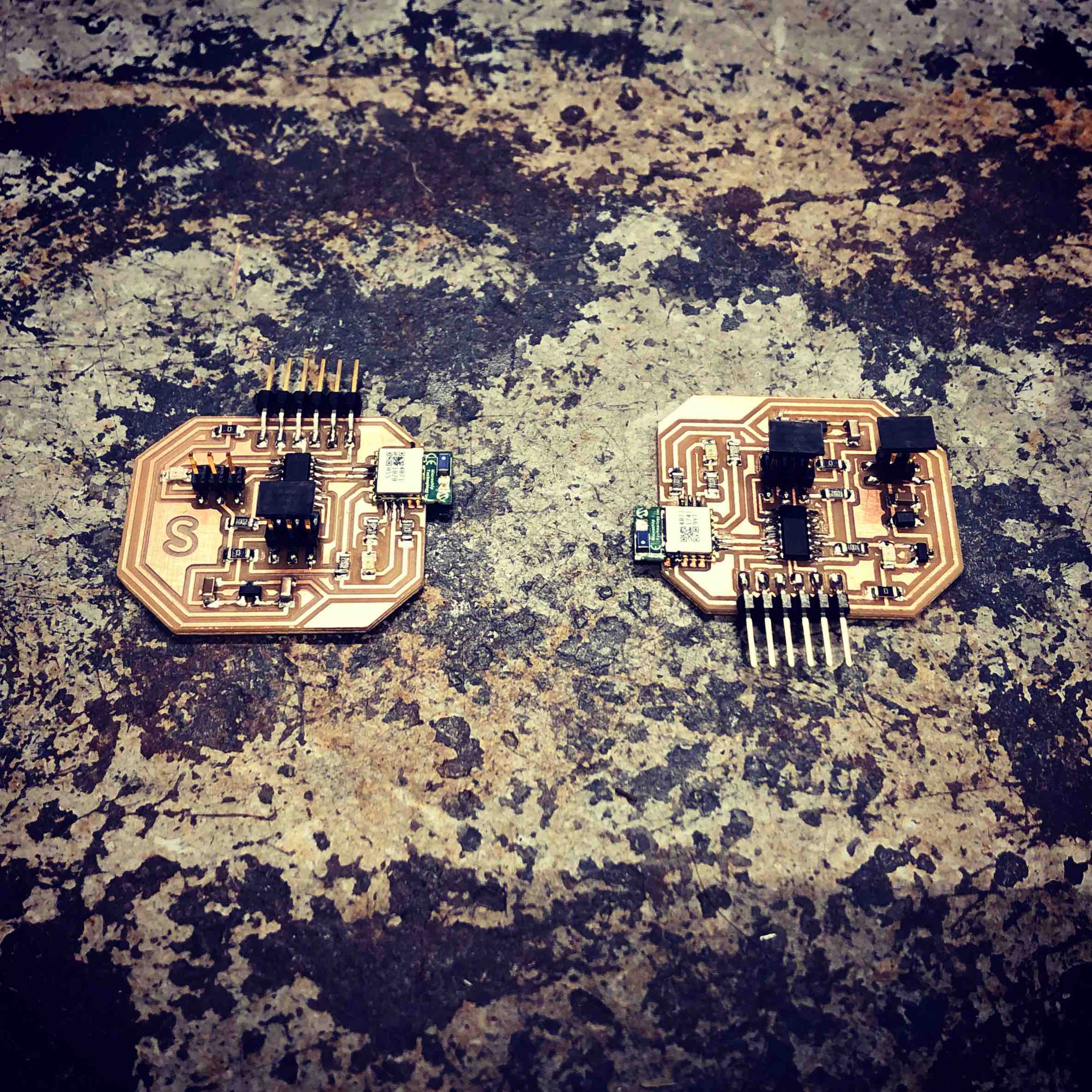
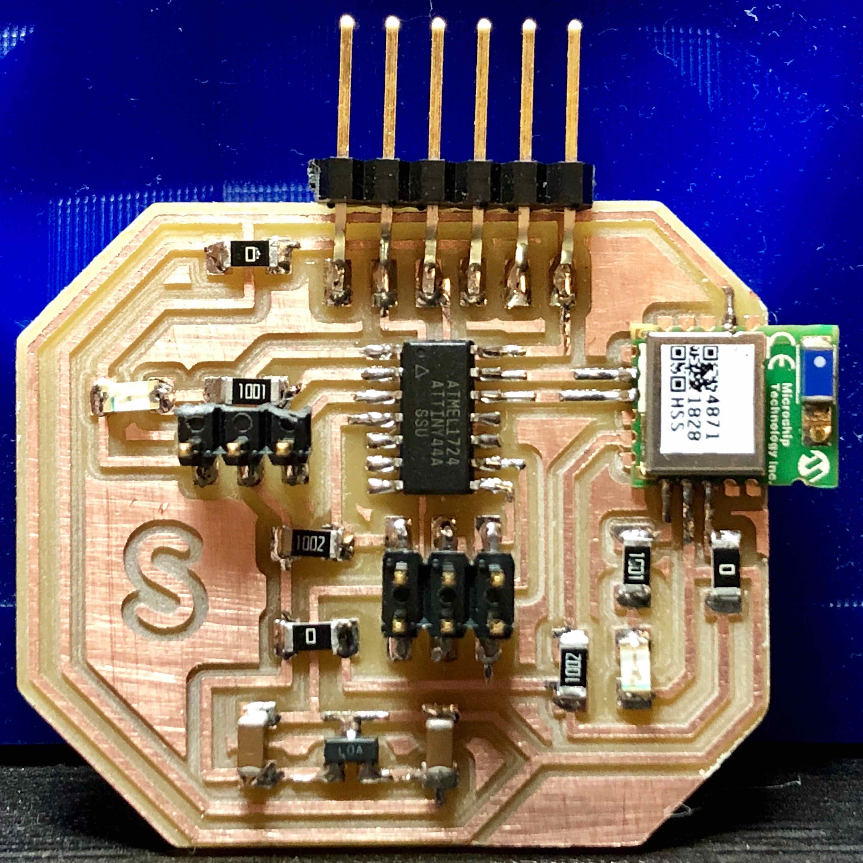
FBelow is the redesigned mini vibration board as well as the redesigned heart sensor board which was also expanded to include a BLE module. The main things to note is the new regulator setup that uses a SOT23 with 1.0uF capacitors on each side. The 3.3 volts the regulator produces is used to power both the ATtiny44 and BLE. 5 volts powers the motor prior to the regulator. Be aware, there are several 0 resistors on the board clearly seen in the close up photos of the finished boards (GND got trapped inside the many traces in several areas on the board). The Meterman validated the 3.3 volts post the regulator and both BLE’s were communicated with on Cool Term. Progress!
Actuator below
Sensor below
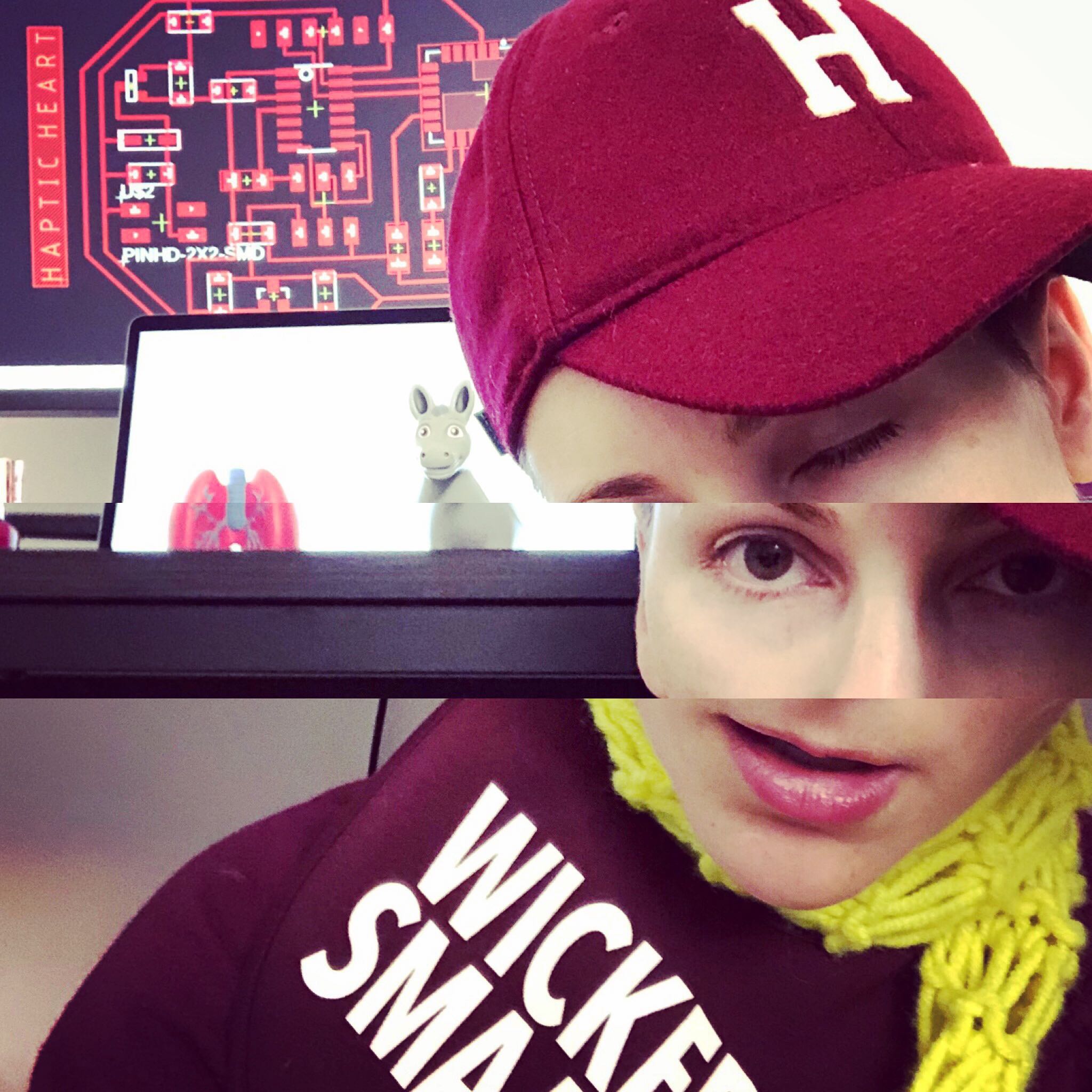
Delerius from 8+ hours on Eagle.
Sensor, left and Actuator, right.
Actuator below
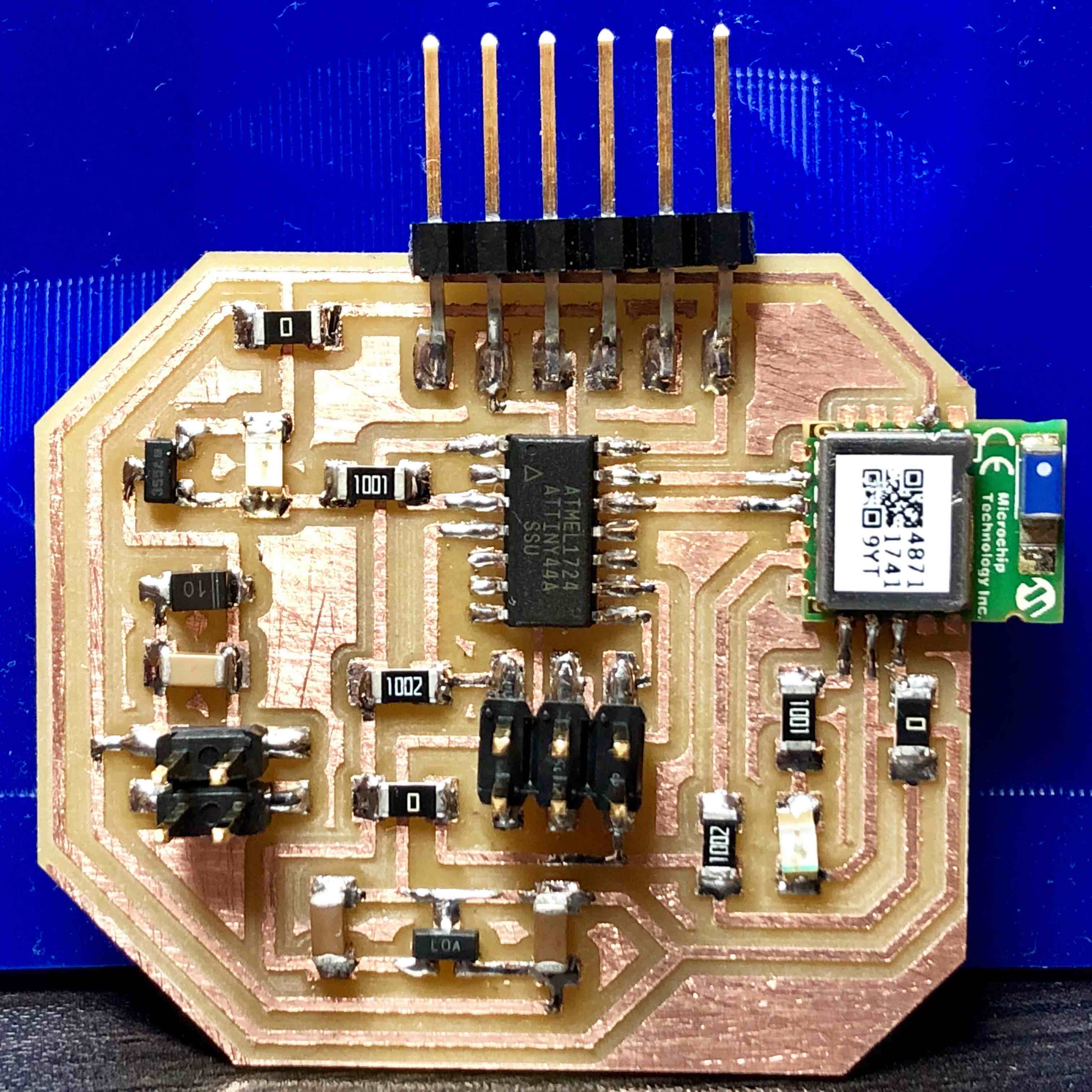
Sensor below
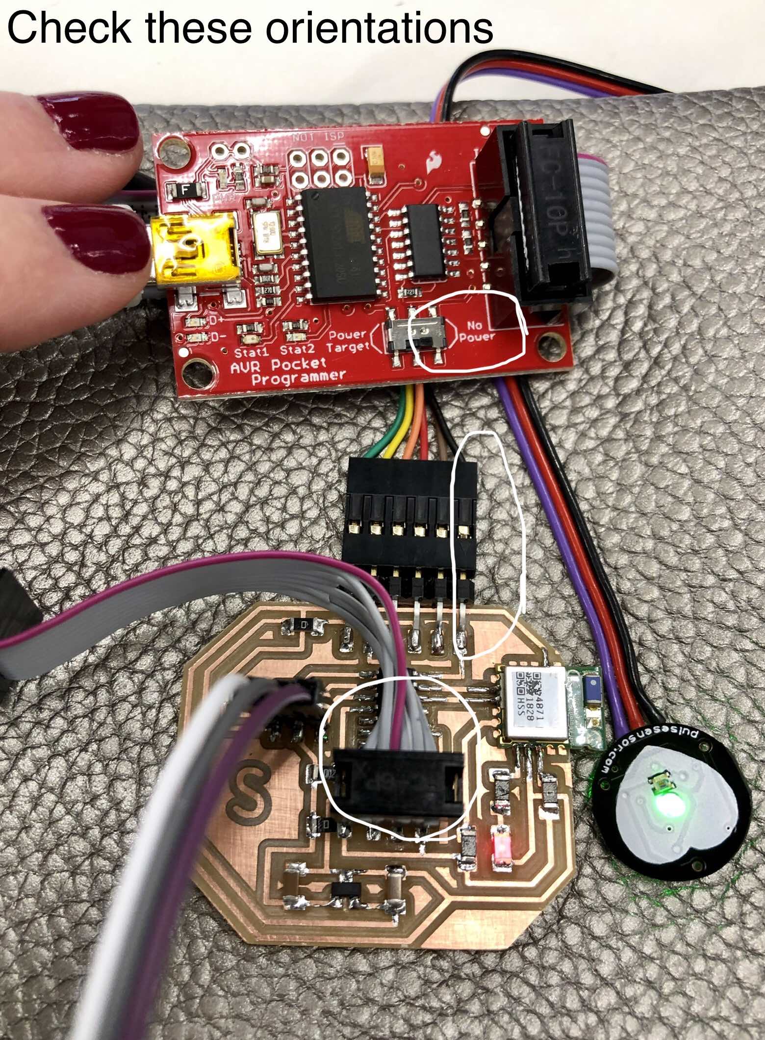
Before moving on to programming the two boards to communicate via Bluetooth, I began with programming them to each do their simple tasks - read the heart rate sensor/blink an LED and turn on and off the vibration motor at two second intervals. This turned into a full day of work as the coding process revealed further oversights in the board design. These were…
Sensor Board Boo-Boo’s- Heart rate sensor pin was not connected to an analogue read pin. Solution: jumper wire.
- BLE module LED indicator went from bright red to ultra dim pink by the end of the day. At one point, a capacitor fell off after dropping the board which went unnoticed. Perhaps this could have led to the module burning out? Solution: new BLE module.
- LED between pin and mosfett put there to indicate when the pin was high worked beautifully but sucked up too much voltage, inhibiting the mosfett from “turning on”. Solution: remove the LED. But this led to…
- Once the mosfett worked, the board began to smoke. This was caused by the diode in the mosfett sequence being oriented incorrectly. This is confusing, because the line on a diode typically goes towards ground. However, in this sequence, it shares a trace with the VCC that powers the motor. Solution: flip the diode 180 degrees.
- BLE module LED indicator went from bright red to ultra dim pink by the end of the day (just like on sensor board). Solution: add more solder to module pins.
A sad update, by the end of the next day, both BLE’s fizzed out, revealed by their red LED’s fading to an imperceptible pink as previously noted : (