Chris Lloyd
MAS.863/4.140/6.943
How To Make (almost) Anything
2019
Week 3: Electronics Production
This week, I set out to create and program a ATtiny45 PCB. At this point, I can't say I fully understand how the board works other than that I am programming something that will program something else :-). Though I am still trying to understand how it works, I developed skills in milling PCB (printed circuit board), learned about various circuit board components, and further developed my soldering skills with small parts. Here is my journey.
PCB Fabrication
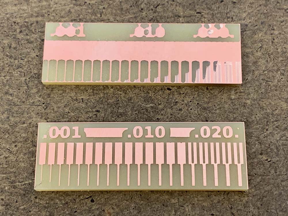
Before milling the board, we experimented with the trace function on a sample file with the mill to understand the difference between bit sizes. Using a sample file 1/64 bit drill (bottom) and one with the 1/32 bit drill (top). As you can see, 1/32 sized drill bits are not well-suited for tracing (which it is used for outline instead), whereas 1/64 was able to capture a lot more detail. To cut details smaller than .015, you would want a smaller bit.

Next I milled my circuit board, following pre-designed PNG files to mill the circuit board on a Roland SRM-20 using MODS.
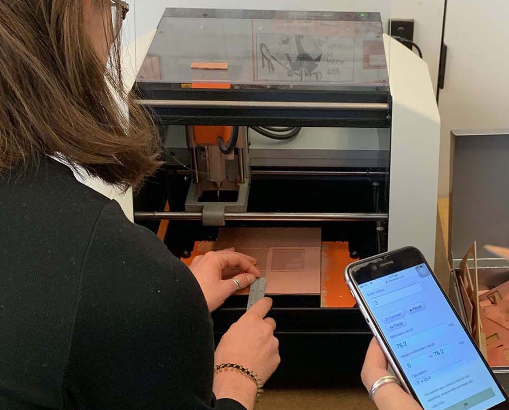
When milling the board, it's important to remember to clean the copper surface and ensure the mill is zeroed in at the edge of the raw board as to be as economical with the material as possible. This appears to be a common issue as people want to be careful, but end up wasting material by leaving too much space between outlines. Below, you can see use calculating where the material begins on the x and y axis.
Assembling and Soldering
I followed the work of Brian to create a FabTinyStar, which is a version of AVR ISP programmer that we have in the shop. We are essentially creating and programming a programmer!
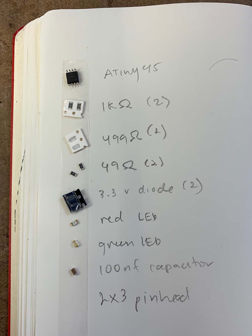
I used the following components:
- 1x ATtiny45
- 2x 1kΩ resistors
- 2x 499Ω resistors
- 2x 49Ω resistors
- 2x 3.3v zener diodes
- 1x red LED
- 1x green LED
- 1x 100nF capacitor
- 1x 2x3 pin header (not pictured, but important)
Though the LED's are technically optional, it was very important for me to use them since this was my first time soldering a PCB and want to make sure I could check easily check that it was done correctly when I completed soldering.
Why surface mounting? I wanted to learn a bit more about this style of circuit making read this article. The most important benefits are reduction in weight, size and and electrical noise. However, there is increase likelihood of breaking the PCB through stress and heat.
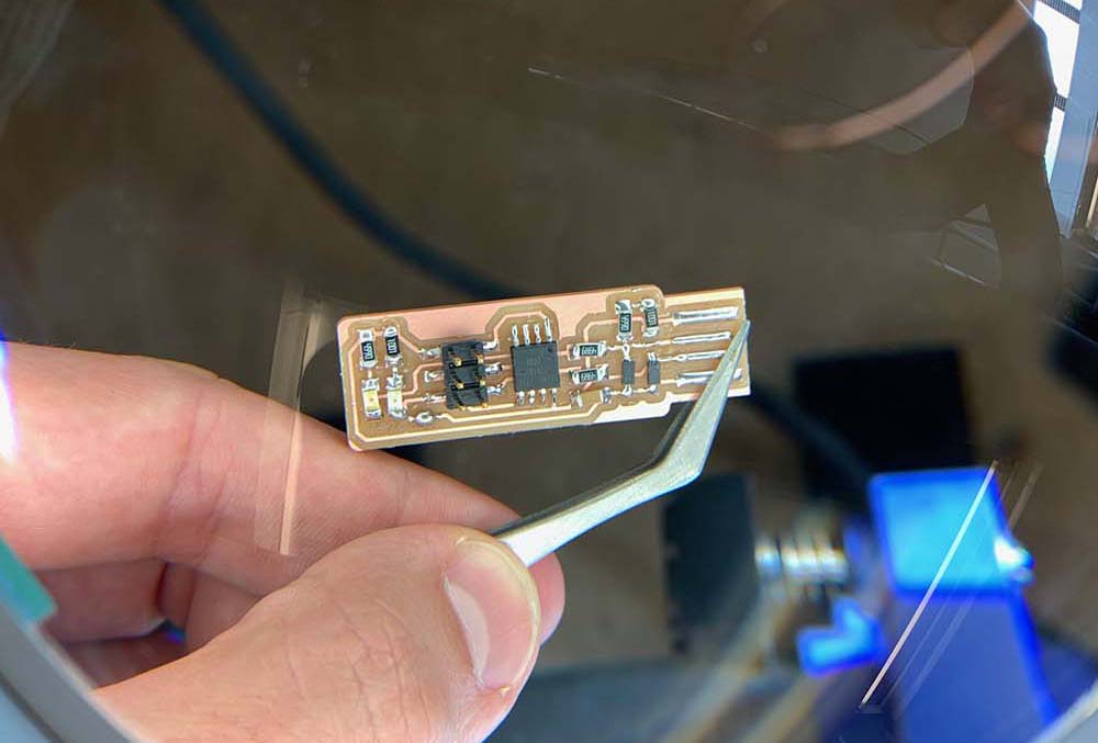
Soldering. I was generally successful in soldering, but would like to try it again as it was not as smooth as it could be. I at first had a hard time soldering directly on the table, so I used an Adjustable Circuit Board Holder like this one. I messed up a few times where the components weren’t mounted correctly and needed to use desoldering wick to remove mistakes. Here is the final result!
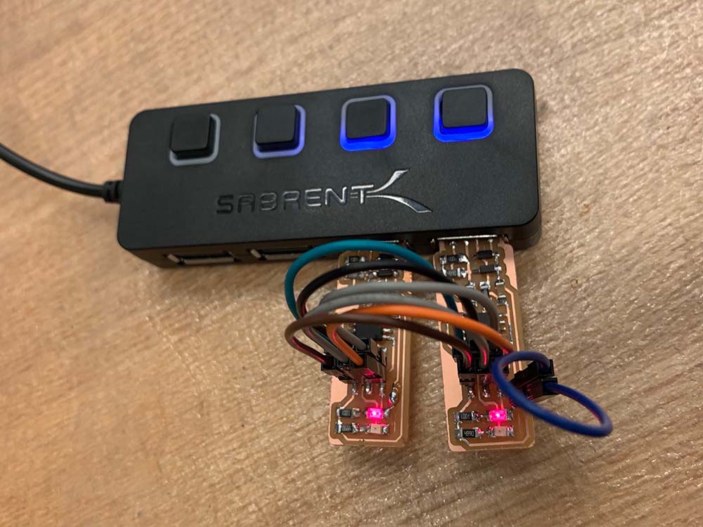
Testing. Before programming, I wanted to check the Red light to make sure that the circuit was soldered correctly. This meant the connections were all good and the orientation of each component was correct. Ta da!

Programming the ATtiny45
Next it was time to program my ATtiny45. Before that, I had to brush up on some beginner tutorials on the command line. Again, this is well documented in Brian's documentation, but I have included a list of the terminal commands I used in sequential order.
sudo apt install avrdude gcc-avr avr-libc make
unzip fts_firmware_bdm_v1.zip
Make (This creates the fts_firmware.hex file that will program the ATtiny45)
After unzipping the file, I had to make a slight change to the Makefile because I was using the Atmel-ICE programmer (PROGRAMMER ?= atmelice_isp)
Mark flash (erase the target chip with the contents of the .hex file)
I initially had issues with this step in the Architecture Shop, which I couldn't figure out, but was able to accomplish it in the EECS shop with no issue. There is possibility that the programmer was malfunctioning or not set up appropriately.
make fuses (set up all of the fuses except the one that disables the reset pin)
Lsub (this is a way to check your work to see if your USB device worked. It showed up!
The final step you can do is to see if the programmer can successfully program another programmer. I didn't personally do this, but observed a classmate in the EECS lab test it out.
And there you have it. I'm still eager to learn more about the fundamentals of designing my own electronics in the future, especially for sensor inputs and network/bluetooth connections, which will be necessary for my final project.