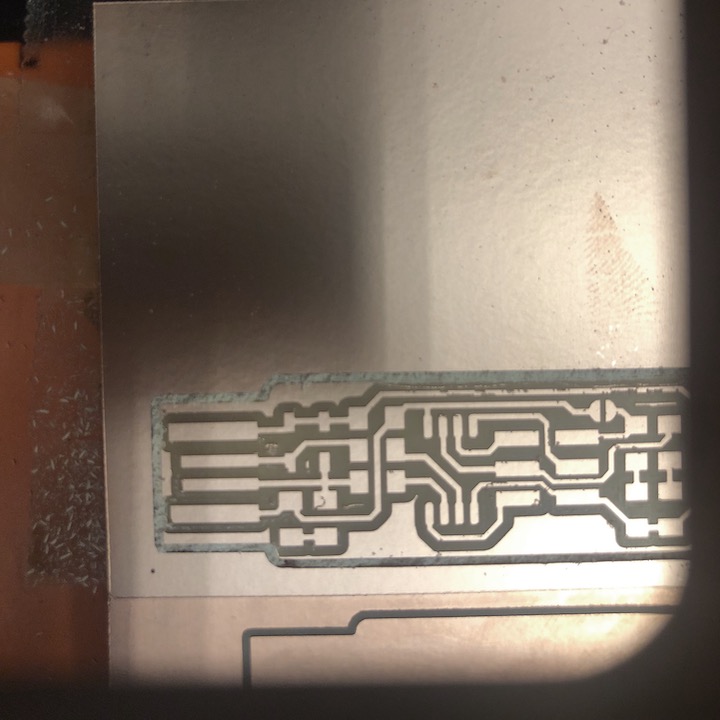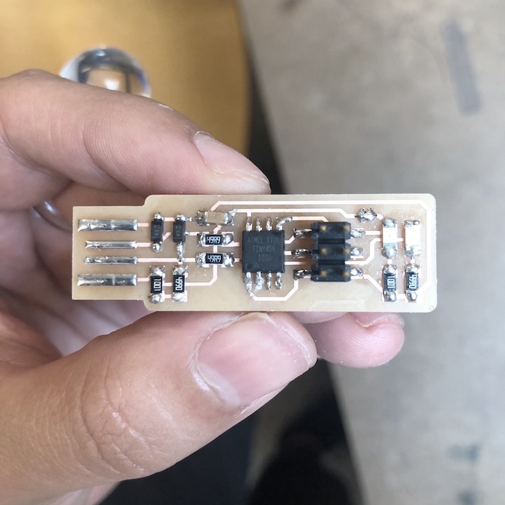
circuit board
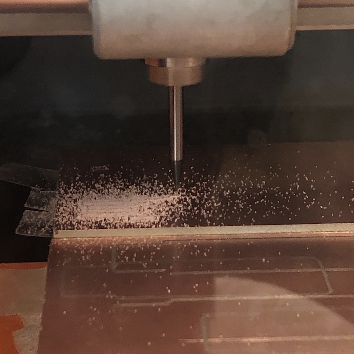
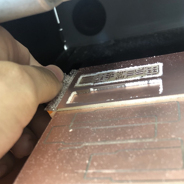
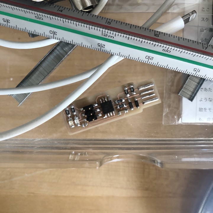
production
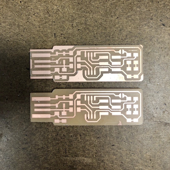
production
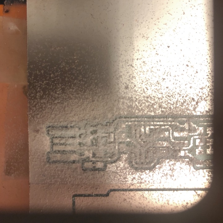
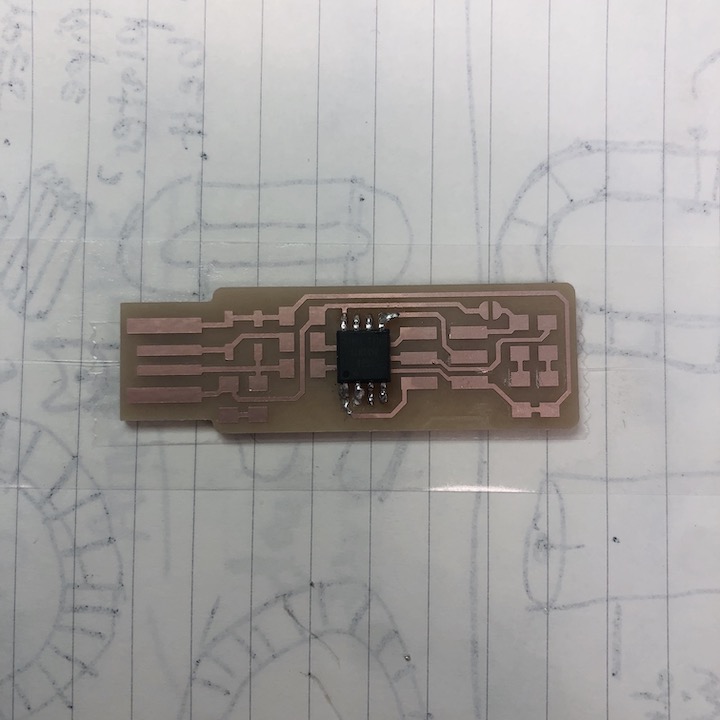
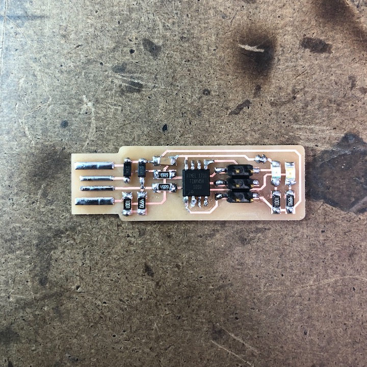
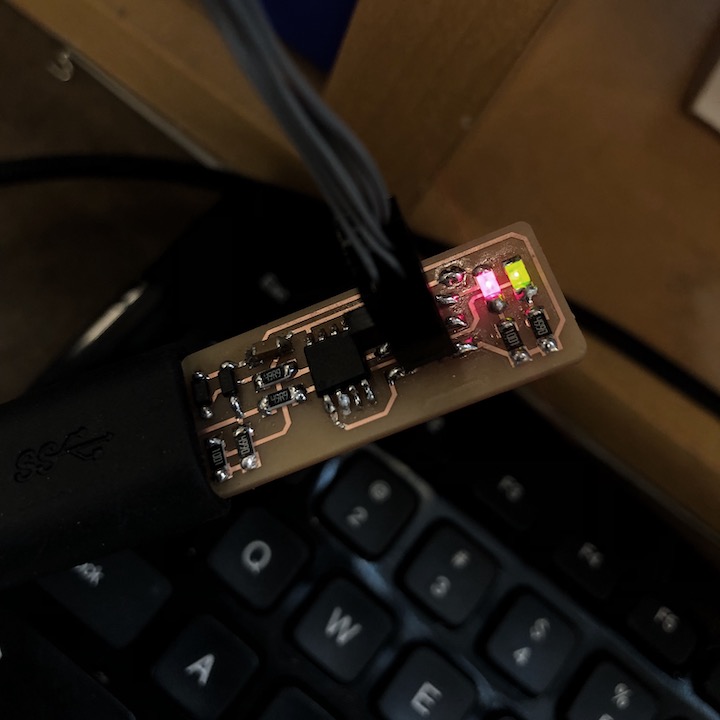
completed circuit board
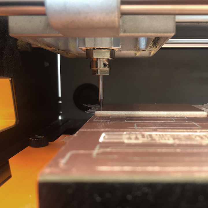
This week we were asked to produce an already designed circuit board in order to get a basic understanding of the general workflow.
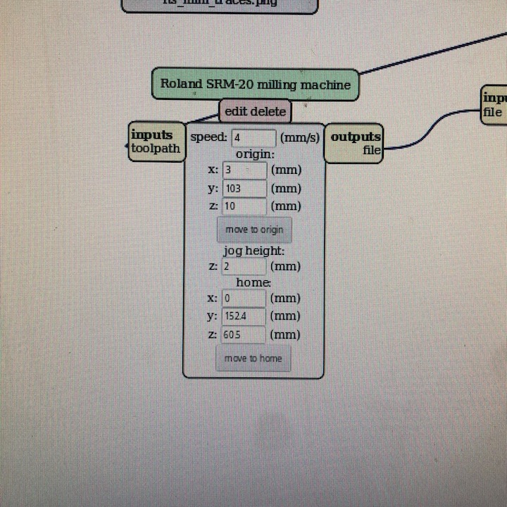
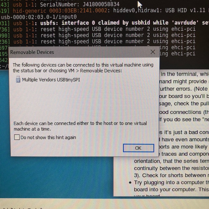
The process begins by milling the circuit board followed by soldering the components to the board, and finally programming it via a computer.
In general, the process went pretty smoothly and surprisingly quickly, though the milling machine was a bit finicky and required restarting multiple times.
This week we were asked to produce an already designed circuit board in order to get a basic understanding of the general workflow.
The process begins by milling the circuit board followed by soldering the components to the board, and finally programming it via a computer.
In general, the process went pretty smoothly and surprisingly quickly, though the milling machine was a bit finicky and required restarting multiple times.