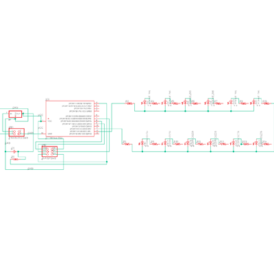
This week was a big faliure! I wanted to start designing a board that will
be part if my final project - party shoe laces. I used the array LED board scheme
that was on the site, and used EAGLE to redesign it in a way that will suit my project.
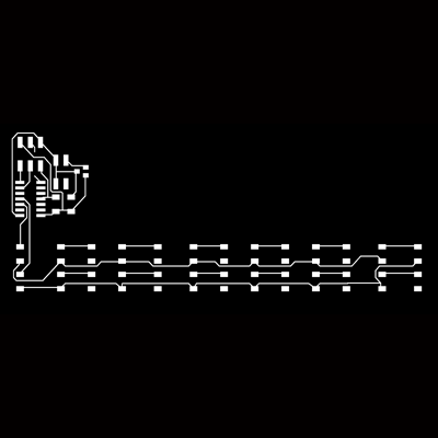
for this purpose, I wanted the LED to be in two long lines, that could fit in to the laces.
Knowing the parts names and location on eagle was much easier this time, so I feel I'm getting
improved in that sense. from the other hand, I had some problems to connect all the parts in eagle
and locating the components so the traces will be good. It took me forever and evantually I couldnt
connect all of them. I left one trace to become a bridge, because I didn't know how to solve this
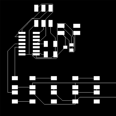
problem. Another problem I had was that at first I didn't load the design rules, so all the traces
were too thin, and I needed to do the whole design part twice. It was time consuming and really held
me back this week. In the photos you can see the wrong scheme with the thin traces, and the one that
I evantually did right.
After spending two days on the design, and trying to understand how this thing actually works,
I decided to challange myself with the intention to cut it on the the vinyl cutter, so
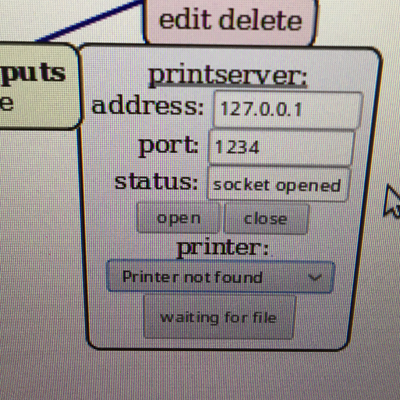
it will be flexible so I could brade the laces around the LED lights. This didn't work well.
From some reason, the Mods couldn't find the roland cutter. I opened the VM, reopened the
mods server, made sure that the device is connected to the system, reopened the Roland,
restarted the whole computer again and did everything from the begining - but nothing worked!
since I worked late (after 7) in the shop, there was no one there that knew how to solve
this issue. I didn't mill the board, hopefully I will be able to do that before class tomorrow!