this week i learned how to setup openocd and gdb in my mac, make my own eagle footprint, burn an arduino compatible bootloader with openocd into an atsamd11, setup the arduino ide, and debug the code inside the samd11 with openocd and gdb.
i followed erik strands instructions on how to install openocd and gdb. since i was only planning on using the atsamd11 and not the atsamd51, i just needed version 0.10.0, so 'brew install opencd' worked perfectly. if i needed to program an atsamd51 i would've had to build from source to get a later version.
to install gdb, i used homebrew as well 'brew install gdb'.
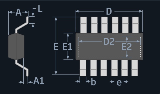
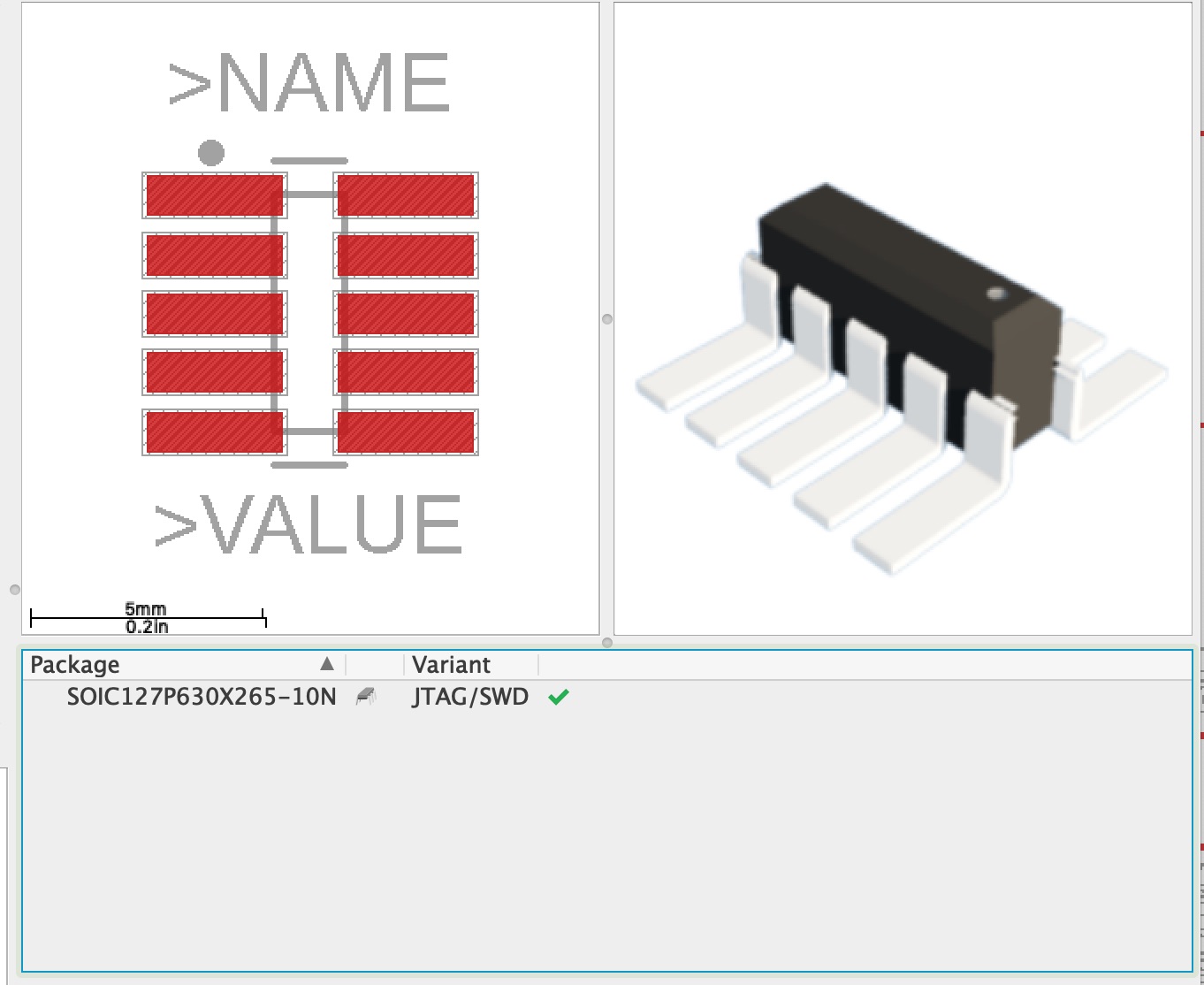
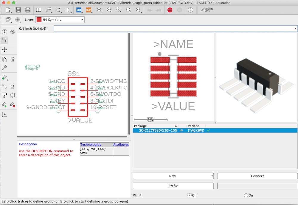
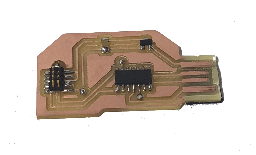
i used neil's atsamd11 hello.d11.usb board as a reference. i avoided using the zero µF by using vias instead. i won't claim smart design but instead lazy design with my prefered usaged of auto routing in eagle. however, this task wasn't trivial becasue i needed a 2x5 header that didn't exist in the fablab parts library. all of them had the pins that were 1mm apart and they needed to be .5mm apart. infact i didn’t even notice this until my second attempt at milling the part. i then spent too much time looking online for the part, and i even milled a third board before realizing that the internet had lied to me. it wasn't until the fourth mill, after i had designed my own footprint. that it worked.
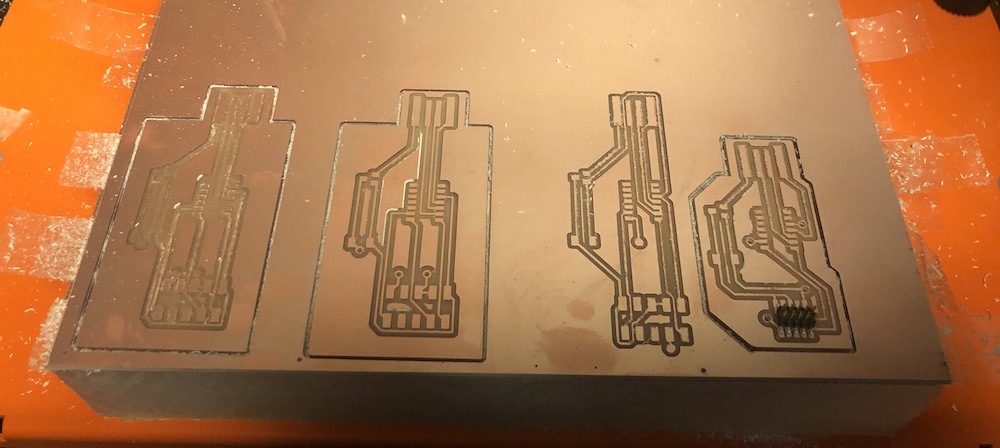
here's my final board layout:

here's my first milled board:

to get the right files, i created a folder that contained the openocd.cfg file and the binary file to bootload.
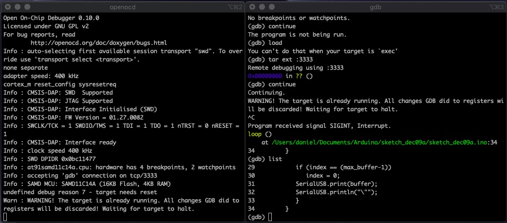
with the board milled and soldered, i plugged in the my board into my copmuter, plugged in an amtel-ice debugger into my computer and then connected the two through the 10 pin header. check to see that both the red and green led lights are lit up in the amtel-ice debugger and then cd to the folder that contains the .cfg and binary file and type 'openocd -f openocd.cfg'. If successfull, you'll get this output:

once the atsamd11 has been bootloaded, you should be able to program it through the arduino ide. there are a couple of steps you need to first take:
write a simple program and test that it works!

so it turned out that i was having problems with my first board where i was able to bootload and program once, but wasn't able to replicate it. i checked every connection with the voltmeter and even soldered usb wires onto the the board to ensure that it wasn't a problem with the usb connection itself.
alas, that didn't work and after going back and forth with erik (he checked my connections, cleaned the board with isopropenol) i decided to just re-mill the board from scratch. instead of adding solder to the usb connection or even soldering the usb wires onto the board itself, i decided to add 3 layers of electrical tape.
one of the main reasons that i wanted to do advanced embedded programming was so that i could learn how to do live debugging of the code in a chip, once i got a board that i was able to bootload and program consistently, i finally had my chance.
i thought i could use the first openocd config file but it turned out that i needed a more minial config file that didn't have any resets or halts, so i made a new one openocd_debug.cfg. i also needed to link gdb with the program's corresponding .elf file. to get it from arduino i had to go to file > preferences and select 'Show verbose output during compilation'. then when you build or deploy the code, the arduino ide will display the location of the .elf file. you'll only need the file name as gdb is smart enough to know where it is.
once you have the correct config file and the elf
here are some handy commands and what they do: