if the computer is off, when you turn it on, the pcb mill will not be connected.
this means the first thing you need to do is right click on ~/Desktop/mods-fs-hotfix/js and click open terminal.
in the terminal, type 'node deviceserver.js ::ffff:127.0.0.1 1234' to connect the pcb mill and the computer.
go to 'mods.cba.mit.edu'
right click in the blank page
click on select program -> open server program -> connect/PCB png
if the computer is on, you can check if the pcb mill is connected by going to the 'WebSocket' module.
take the pcb board that will be milled, put doubled sided tape evenly on the back of it and place it in the bottom right corner of the sacrificial board.
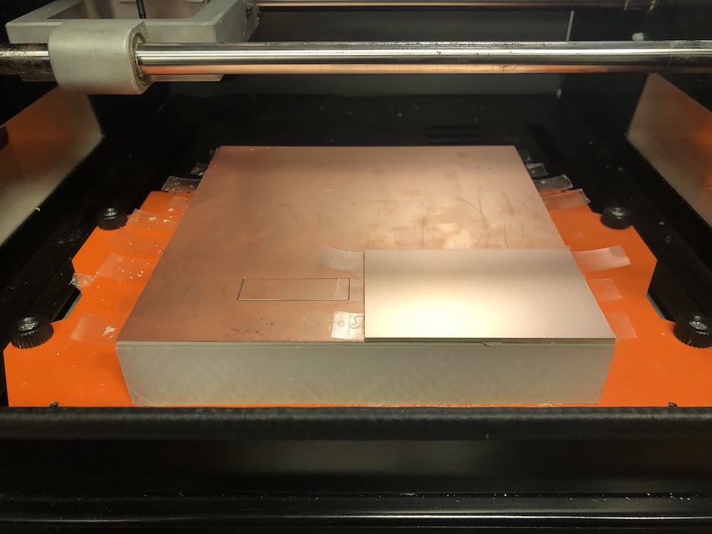
in the 'Roland SRM-20 milling machine' module, under 'home' make sure the z value is a conservatice number such as 60mm and then click 'move to home' button to ensure that the mill is away from the pcb board

with the position of the drill at home, place a 1/64" drill bit in the the drill head.
there is a hole on the side of the drill head that contains a small hex screw that you tighten until snug. That means as soon as you feel some resistence, give it a tenth of a turn more and STOP before you kill the thread.
in the 'Roland SRM-20 milling machine' module, under 'origin' make sure the z value is a conservative number, I chose 20mm. you want to make sure that the drill bit head wont hit the pcb board as it moves along the xy plane. this may break the machine, not just the drill bit
choose x and y origin values that will line up with botton left of the pcb board, in my case x was 110mm and y was 10mm, and click 'move to origin'. If the drill head doesn't land on the bottom left of the pcb board, change the x and y values until it does.
now you need to zero the z value.
loosen the drill bit while holding onto it so that it doesn't drop on the pcb board and bring it down to the pcb board. then while holding the drill bit firmly on the pcb board and tighten the hex screw snuggly. if you don't hold it down, it will ride up as you tighten.
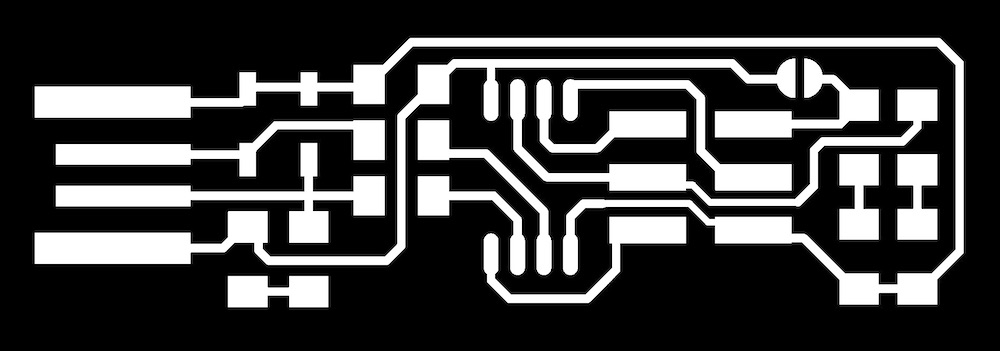
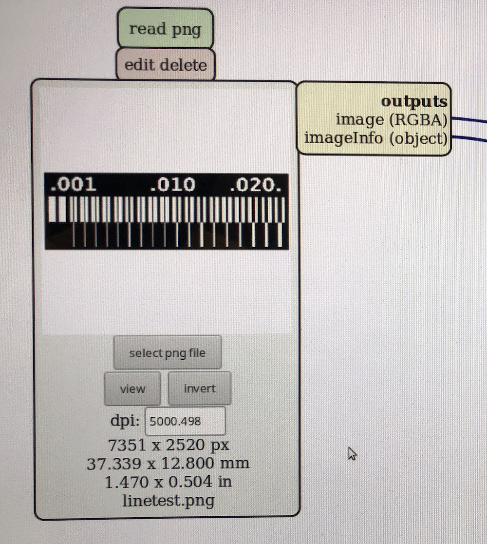
pick the png of the file containing the board you want to mill in the in the 'read png' module by clicking the 'select png file' module.
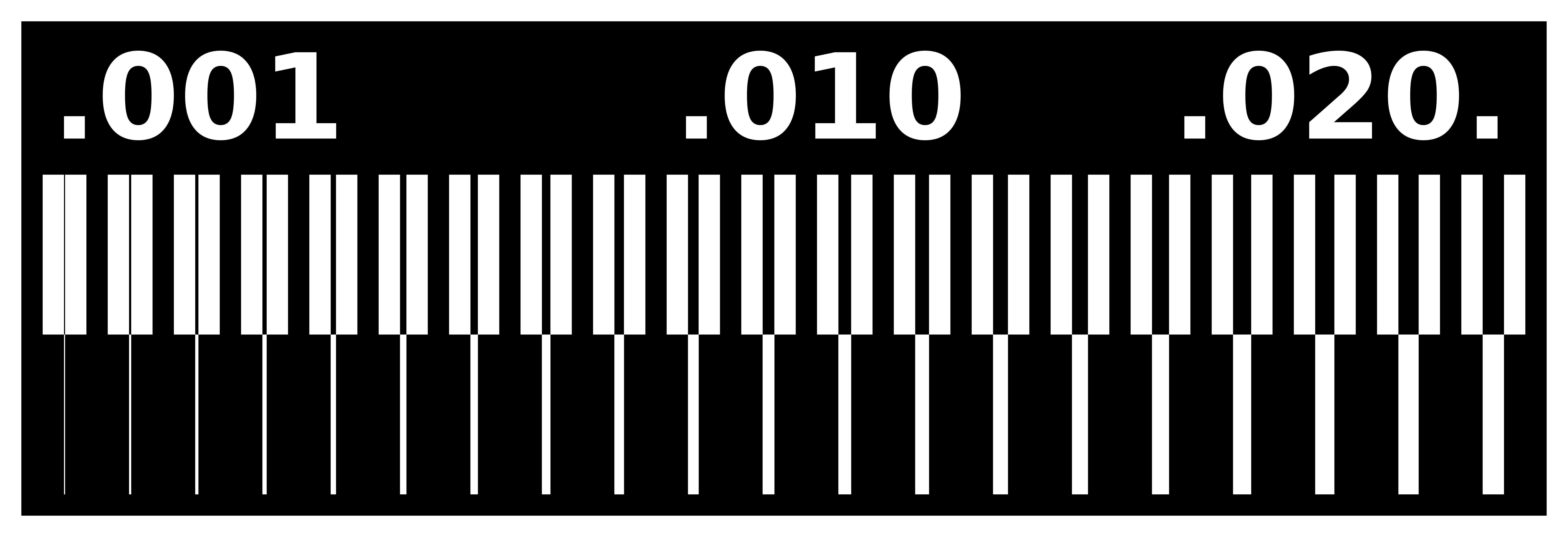
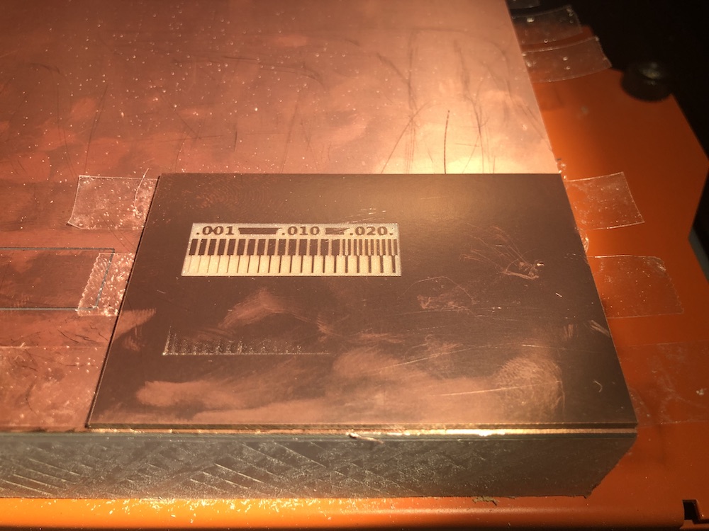
I picked the file I used to characterize the design rules of the milling machine.
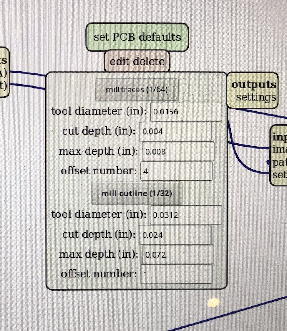
in the 'set PCB defaults' module, look at the values bellow 'mill traces (1/64)'.
because the drill bit is 1/64", make sure the value for 'tool diameter (in) is .0156. the 'cut depth (in)' is the depth that one pass of the mill cut, which i set to .004. the 'max depth (in)' is how much material to actually cut. i set it to .008 meaning that with a cut depth of .004, the mill will have two pass throughs.
after any changes to the values, make sure to click 'mill traces (1/64)' to propogate the changes.
in the center module click 'calculate' to calculate the mill paths based on the png and mill traces.
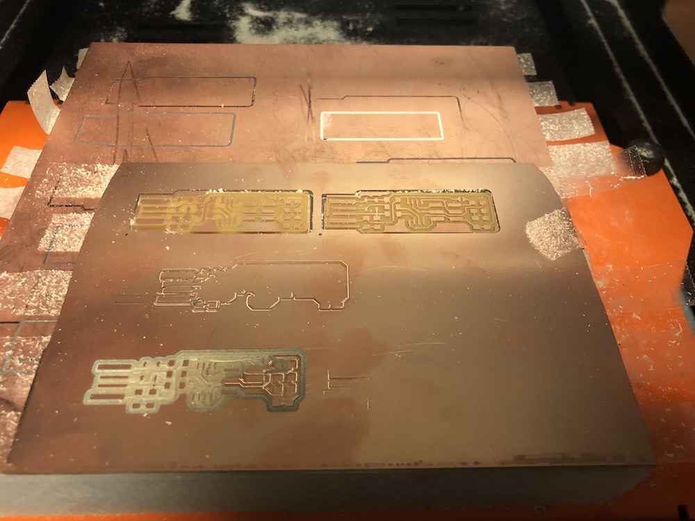
in the 'WebSocket' module, a button should change from 'waiting for file' to 'send file' which indicates that the png has been successfully calculated. click the button and the mill will start.

when the milling is done, the drill head will move automatically to the home position. to cut out what was milled from the board, you will have to mill one more time.
repeat steps 7 through 13 with some minor differences. in step 7, use a 1/32" drill bit. in step 10, choose a png file that outlines the perimeter of the cut. in step 11 use 'mill outline (1/32)' with a 'too diameter' of .0312, a 'cut depth' of .024 and a 'max depth' of .072.