Week 5: Electronics Design
Designing a "Hello World" board
This week, I am beginning by designing a "Hello World" board complete with an LED and button, based off of the reference board.
I decided to use KiCAD, though in the future I want to try out EAGLE. I mostly went off of Neil's introduction video, so there was a good bit of trial and error to get it all working end to end.
I imported the KiCAD libraries and asked around a bit to figure out exactly which components corresponded to the resistors, capacitors, ATTiny boards, etc. that we had available.
I had one issue when going from logical net to board footprint layout, where I thought the libraries hadn't imported.

The issue was that I wasn't double-clicking on the component mapping on the right side of the mapping screen, so it wasn't applying the mapping despite it being the suggested result.
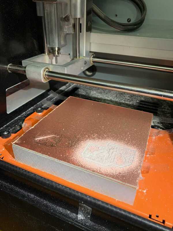
I tested out my board etching layout, and it seemed good.
Just as I was about to begin milling, I noticed I was missing the resonator component entirely. I went back to add it, and found that I had some trouble getting the wiring to fit. I ended up lowering the clearance I had set a bit (so it could fit 3 instead of 2 etchings down the ATTiny board), closely following the example board layout, and moving my LED and button to pins on the left side of the board. This helped avoid any crossing-requirements.
When I plugged one of my outline etchings in to Mods to test it out, it unfortunately seemed to have doubled etching lines, though that may have just been an artifact of the milling solver that would have been fine. Just to be safe, I re-did the outline as a rectangle.

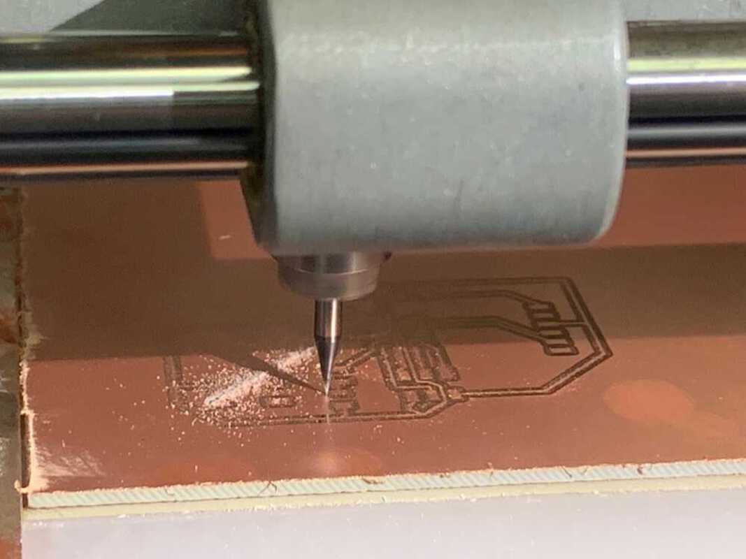
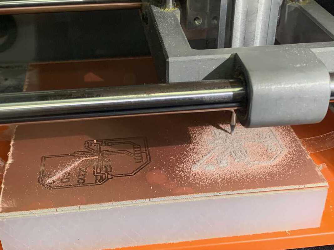
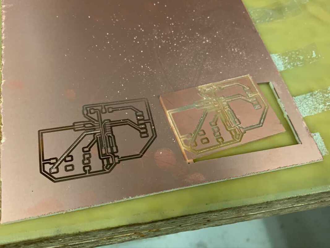
Milling: Round 2
I was hoping milling would go smoothly, but unfortunately I had trouble with my first stab at the board.
It seemed as if the left side of the bed might be lower than the right side. I had the same issue the week we initially did milling.
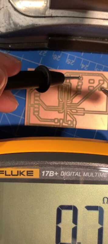
I was initially worried my board's milled wires were not actually connecting. I tested it out and found it was fine. It may be the case that I just had to de-burr them.
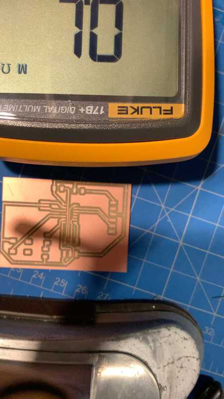

Zach helped me A/B test my board with a known working programmer setup, and we confirmed it had an issue. We noticed a tiny cross-over where a bit of copper was crossing over, connecting two lines and causing a short. We scraped that off, and then Zach noticed another issue -- I was missing a connection from the ground of my capacitor to the ground of the ATTiny board.
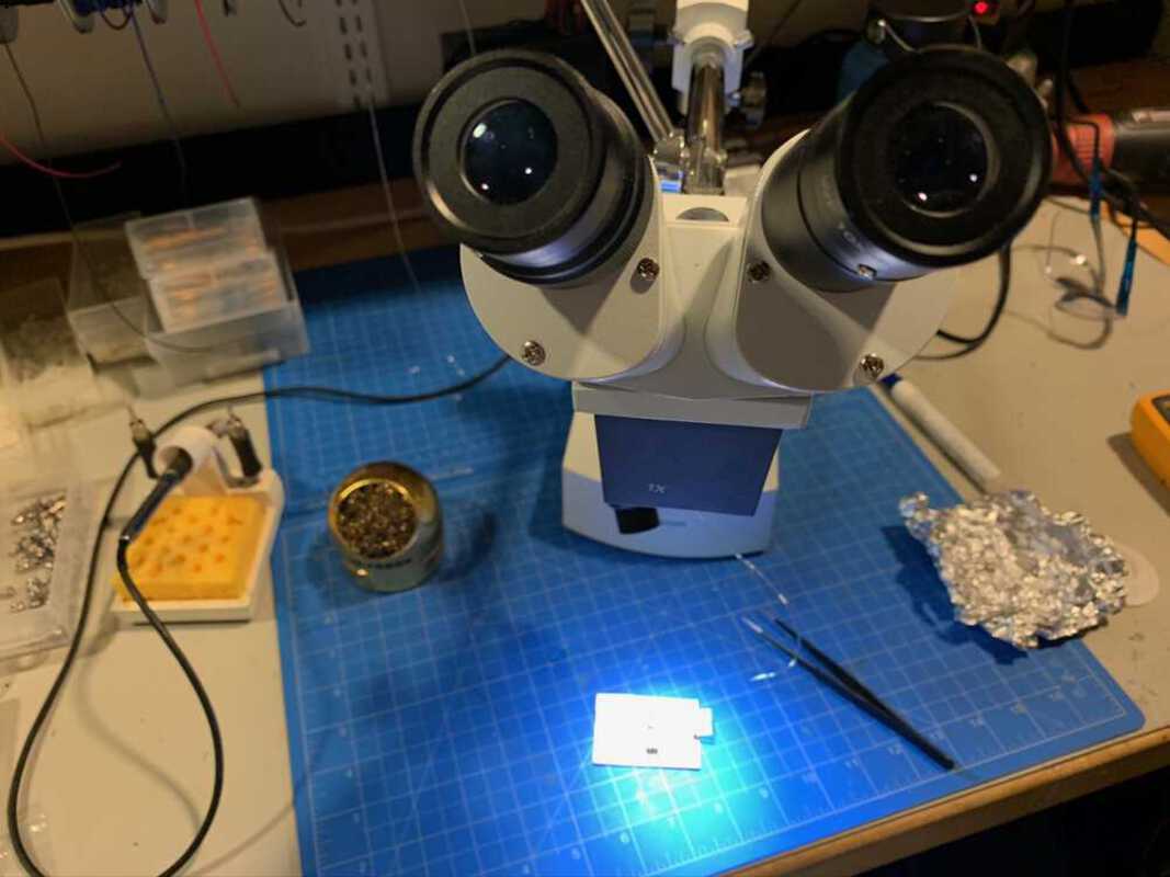
Zach showed me some awesome tiny wire and a technique for using the soldering iron to remove the outer insulation and pre-coating the wire with solder in order to have a very small joint.
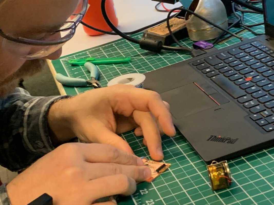
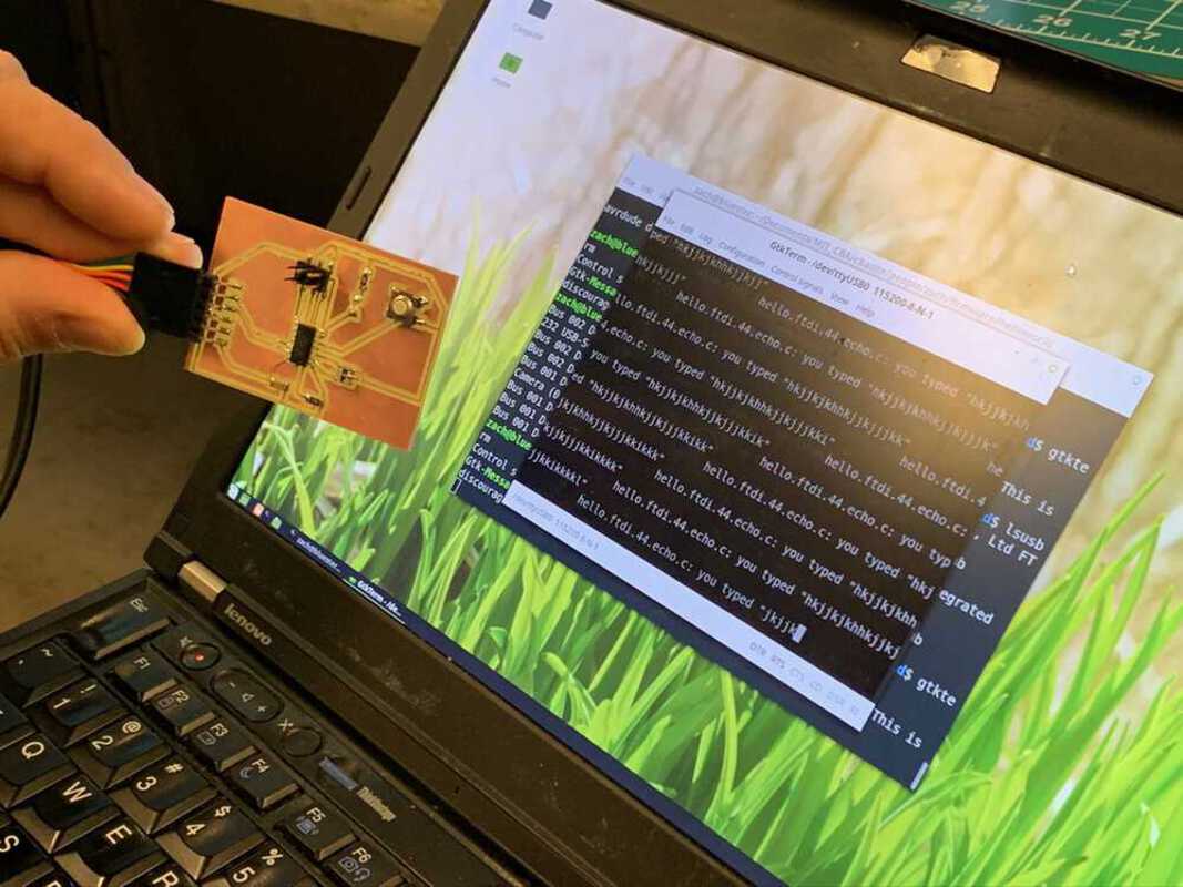
I also had the pleasure of hooking my board up to Zach's franken-programmer. It worked like a charm.
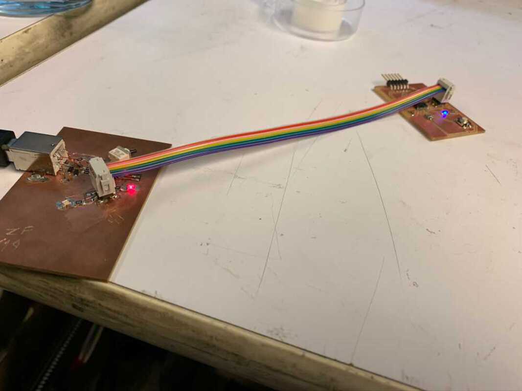
Here we tested the stock program out on Zach's computer.
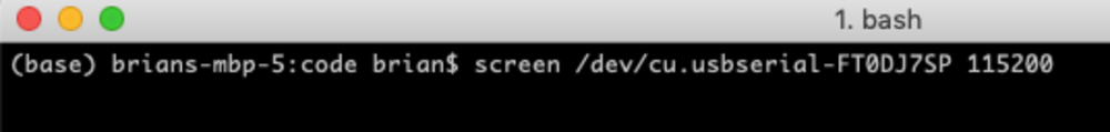
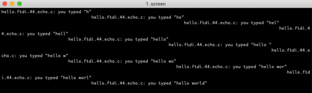
Back in my lab I hooked it up and tried it out using screen.
Next up I'd like to make my board's button toggle the LED on and off. Unfortunately I got finished right under the wire this week so didn't have time to play around with changing up the program for it!