Week 9: Input Devices
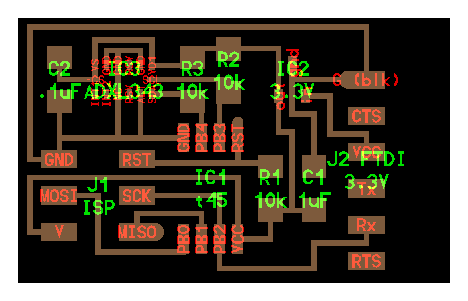
For this week's embedded programming assignment, I decided to mill a board with an ADXL343 accelerometer and test out some of the logic I will use for my final project — programmable smart juggling balls.
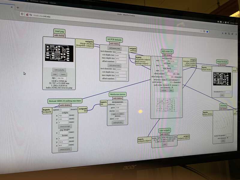
I started out by milling a board based on Neil's reference traces.
I had trouble getting the mill to cut properly. This happened in previous weeks, too!
I made sure to follow all the right steps when z-axis zeroing the mill:
- Make sure you zero at the same x/y location you will be milling
- Tap the mill on the board a couple of times in order to loosen/shed any remaining material left over on the mill from previous cut and avoid zeroing on top of e.g. a fleck of material
- Hold the mill down with your left hand as you tighten it with your right hand
It began cutting a tiny bit on the first pass, but then started just etching (even on subsequent passes, down to depth 0.012!


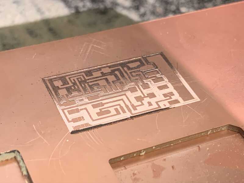
I suspect it might have something to do with the sacrificial layer / angle. This board had been cut a few times as well, so it's possible that cutting near where previous boards had been milled could result in a less solid location for cutting?
Ruling out the mill itself, Aubrey did a cut on the same board right after, just in a different location (bottom left).
Possible there's something wrong with how I am zeroing the mill. Bit of a mystery!
While I was waiting for mill time, I collected the components I would be stuffing later:
Update: Aubrey called for a mill replacement because it ended up going bad shortly after her cut. It's possible it was partially due to a bad mill.
Then I stuffed the board with the right components.
- http://academy.cba.mit.edu/classes/input_devices/accel/hello.ADXL343.png
- http://academy.cba.mit.edu/classes/input_devices/accel/hello.ADXL343.reflow.jpg
- http://academy.cba.mit.edu/classes/input_devices/
We had two solders in the lab, one of them worked a lot better.
I held it in place with alligator clips on arms.
On the actual device itself, I found quickly wiping solder across the pads would result in a good amount.
Then I attempted the reflow!
Attempt #1: Let go of the to let it fall into place. Blew away!
Attempt #2: Same thing!!
Attempt #3: Squeezed too hard, popped out of tweezers
Attempt #4: Success! It went down!
Then I attempted to pick up the board to see if it was done. Ouch! The outsides of the PCB were still really hot.
The Vantage Cutting Mat I was soldering on top of then also began bowing upwards (a pocket around where I was heating), and retained a lot of heat.
Attempt #5: It was hard to tell, but it seemed a bit like some of the joints weren't quite lining up. I tried to align it a bit better.
Some of the joints seem to be cold-solder style. I'm not sure if it will ultimately work, but I will continue plodding ahead with soldering this!
When I was attaching the FTDI header, I put down both the top left and bottom right solder pads at the same time. This caused an issue where I couldn't get it to be flat flush with the board. I used the heat gun to remove it.
After all that, I realized it must have been an optical illustion (shadow + depth of mill traces).