Electronics 101
I have no background in electronics so I took some time this week to learn the basics of electronics.
Here is copy of my notes on BASIC CIRCUITRY. These notes cover different electronic components, what they do and how they look in circuit diagrams.


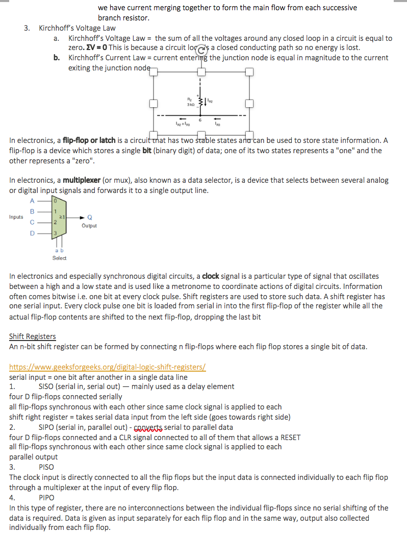
Here is a copy of my notes on BASIC ELECTRONICS. They cover laws of currents and voltage.

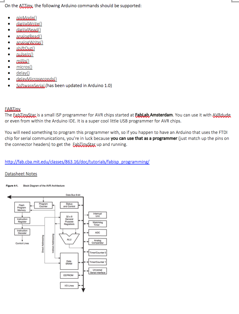
Finally, I took a set of DATASHEET NOTES related to microcontrollers and specific to the board that we are making. This set of notes also includes my notes on our ATTINY44 Datasheet.


Board Design
Now that I understood electronics much better, I was ready to begin creating my board. The first step was to design the board in Eagle.
I decided to make the board depicted in hello.ftdi.44.py. In my notes above, I explored the of this board and the function of various components, particularly its ATTiny44 microcontroller.
(1) I downloaded Eagle and installed the fab.lbr which provides us with all the parts in the FabLab. I also added in the Sparkfun libraries.

(2) The next step was to lay out all the required parts on the board. I used the board schematic provided to us as a reference, and put corresponding parts from the fab library on the board:

(3) The next step was to lay out the schematic using the Eagle UI. First I put in a frame to keep the process neat. Next, I placed the boards and joined them using the Net tool. It took me a few revisions to get all the circuits parts joined correctly.

A few things that initially confused me but I later figured out were that:
- The difference between the AVR ISP SMD and the FTDI SMD HEADER is that the former is used to program the microcontroller and the latter is used to talk to it once it has been programmed. Notice the AVR ISP SMD is connected to many pins on the microcontroller and the HEADER to two.
- The resonator is not actually connected to the LED. They are just both connected to ground.
Our assignment was to add a button and an LED.
I added a button and connected it to an unused pin on the microcontroller (Pin 11). I added a pull-up resistor to this part of the circuit to prevent Pin 11 from floating when the button was not pressed and so that when the button is pressed, current from VCC would flow through but that the power and the ground would not directly connect through the button (and cause shorts).
I added an LED and connected it to an unused pin on the microcontroller (Pin 10). I added a current-limiting resistor to this part of the circuit so that the LED would not draw excess power.
I connected the LED to the button.
I connected the LED to ground so that when the button was not pressed, the LED would not be lit up, but that when the button was pressed the LED would light up, and that this would be controlled by the microcontroller.
(4) I switched to Board view in Eagle. I then placed all the elements of my circuit on the board.

(5) I prepared to route the board. First, I loaded in the design rules provided in a .dru file to us by the TA's. This told the program the appropriate sizes and closeness for paths to make a board we could mill in our fablab.
I used Autorouter to route the board and got a 100% clear path.

(6) Exporting PNGs
I installed ImageMagick and used the code in eagle_scripts_eagle_png.py by running the command python eagle_scripts_eagle_png.py hello_world_0.brd to generate the trace and outline PNGs.


Board Production
I milled and soldered my board.
