My final project involves an input microphone. Mic Circuits
I found this resource< on mic circuits quite helpful for understanding the fundamentals of how these worked.
The Mic is connected to:
A resistor (R7 on schematic below) that is connected to VCC — to power the mic.
A capacitor (C3) — that blocks DC voltage on the input signal and allows AC to pass through. When we speak into a microphone, our voice or music is the AC signal. This is the only part of the signal that we want to pass through to output. The DC signal is only used to give power to the microphone; we do not want it to appear in output. The signal that flows through C3 is the one that feeds into the OpAmp and eventually the microcontroller. Overall, the sound signal travels through the Mic, then the Op Amp, then are read into the microcontroller.
Electronics of Sound
I also took some notes from this resource on the electronics of sound.
Design
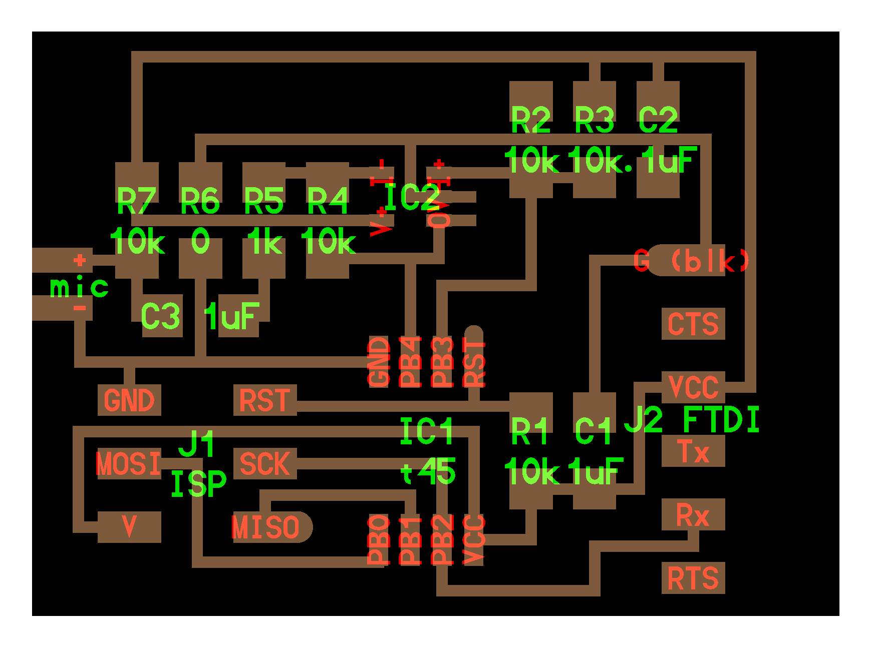
I started by taking a look at Neil's board design for the Electret Mic.

I made some notes on the input-specific components of this circuit.
Op Amps
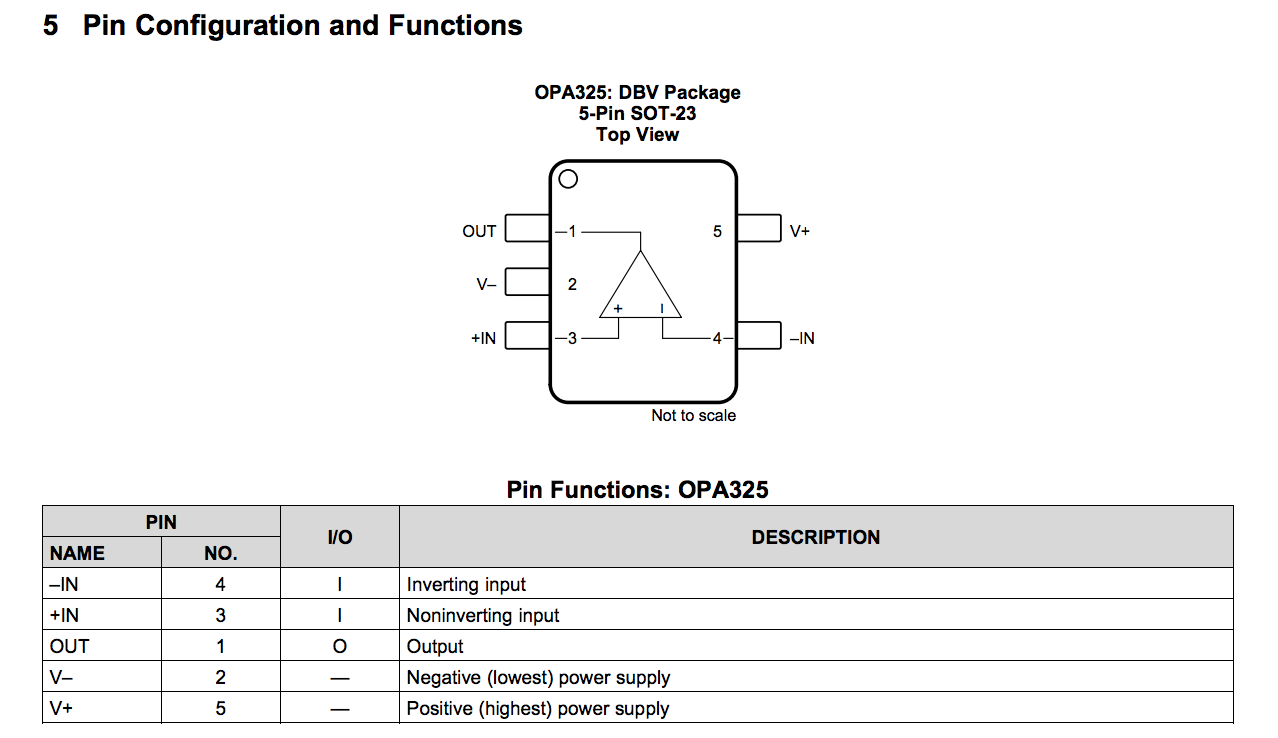
An Op Amp is a voltage-amplifying part. I first looked at a datasheet for the OP AMP SOT23 5-Pin Amplifier. This type of amplifier uses a SOT23 (Small-outline Transistor).
I noted the pin configuration for the Op Amp.

I noted that Pin 5 was VCC (V+) and Pin 2 was GROUND (V-).
Pin 1 was for Output
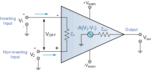
- Pins 3 and 4 are the inverting and noninverting inputs. I learned that these two input pins are used to control the output. An OPAMP multiplies the voltage difference between it’s noninverting and inverting inputs with a number A and outputs it: Vout = A (Vin+ - Vin-). We connect these to the free Pins 3 & 4 on the ATTiny45 microcontroller.

I designed the schematic for the board on Eagle.

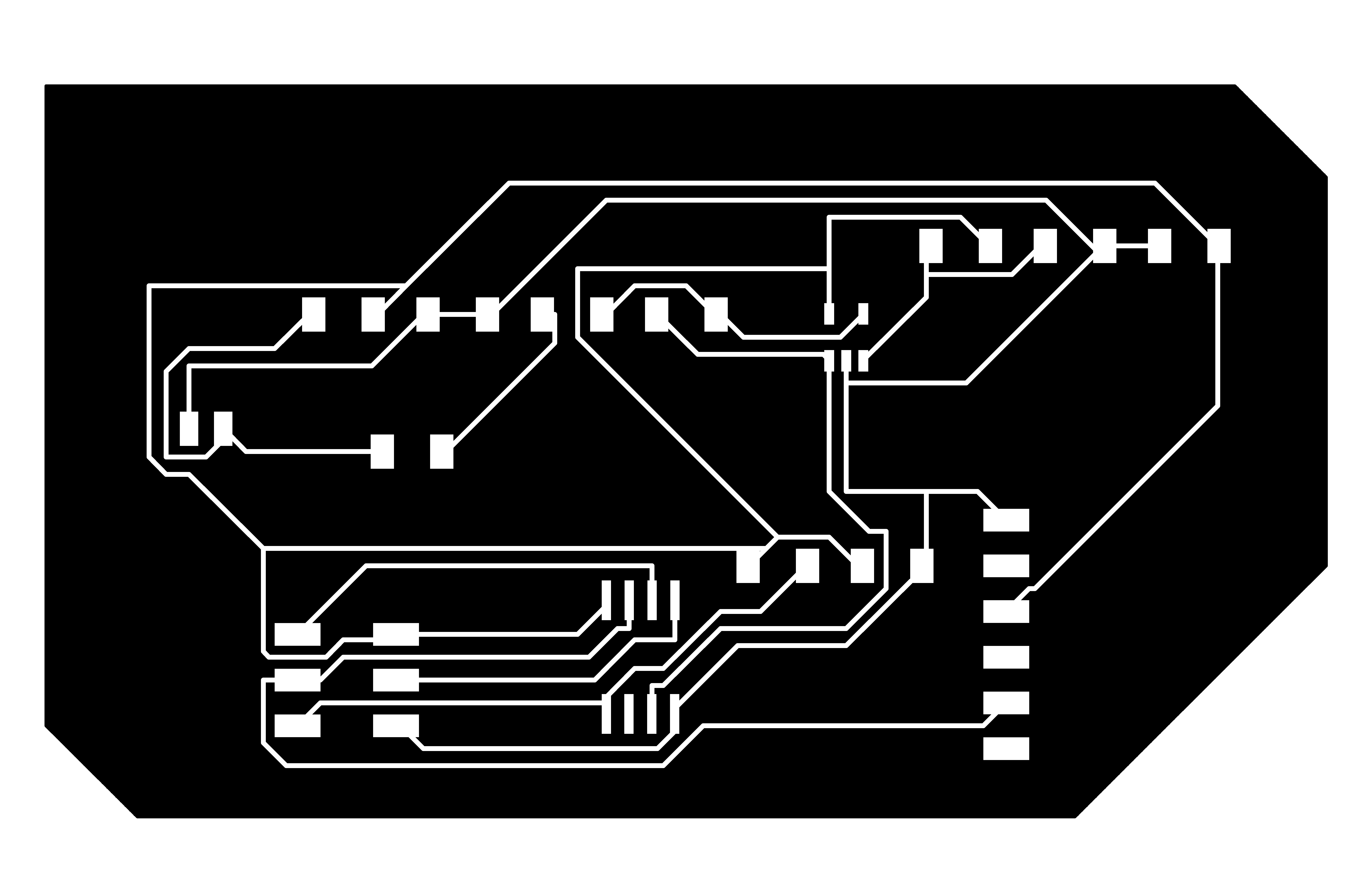
I switched to a board perspective and connected the parts with traces.

Production
I milled and soldered the board.


Programming