Milling
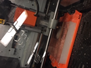
The first step was to mill the circuit on the SRM-20 with the correct settings.
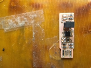
I first inserted the 1/64 end mil tool to cut the traces of the circuit. I then set the program to cut the PNG file of traces with 0.04 cut depth and 0.08 max depth and 4 offset, which was arrived at after some testing. I then moved the machine to the origin and lowered the end mil, then performed the cut.
I next inserted the 1/32 end mil and cut the outline, with three cuts to max depth 0.076.
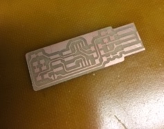
I then vacuumed up the milled bits, and washed the circuit with soap and water.
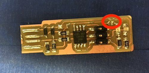
While printing the boards, I did learn that the right side of the PCB board is somewhat more skewed and the left side yielded a cleaner cut.
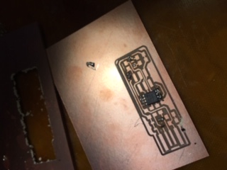
Soldering Learning to solder took me a few tries. On my first attempt, I accidentally peeled off some of the copper with the solder tool.
I then practices using a partially milled board.
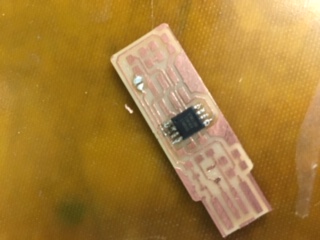
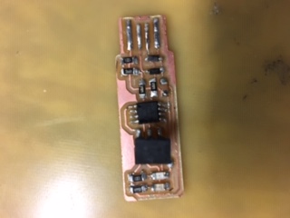
On my second try I successfully soldered all the parts in place.
However this second board did not successfully program as I received the error rc=1. I worked with a TA to check all the components were correct and test the resistors.
I created a third board, by which time I had the process pretty much memorized. This time the soldered bits were cleaner.
Programing
In order to program the board, I first installed necessary software on my computer.
Next I connected my programmer to my computer and the blue avrisp2.
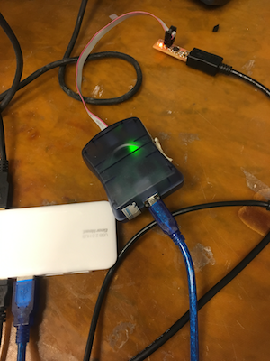
I ran the make flash and make fuses commands.
I checked that the device was recognized as a USB.
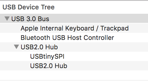
I disconnected the solder bridge.
Now I had a working FabTinyISP programmer.