
I worked with Zach, Aubrey, Jiri, and Patricia on the group assignment.
We used an alternate mill because the one we had been trained on was in use. We had some issues establishing the web socket connection when starting mods from the commandline. This was fixed, eventually, by turning the mill on before attempting the connection.
Once we were up and running with mods, we loaded in the test pattern and set it two two offset passes. We were using the 1/64 inch end mill, with 0.004 inches cut depth.
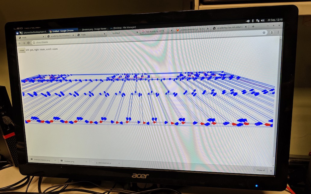
We confirmed in mods that the toolpath was indeed going to take two offset passes. (It was only now that I actually understood what this meant; before I had been confused by thinking it was about depth rather than potential maximum width.) Mods confirmed visually as follows:
We then cut the test pattern. (This felt very exciting.)

We then also switched in the 1/32 inch end mill to cut out the outline. We ended up with the following test pattern result:
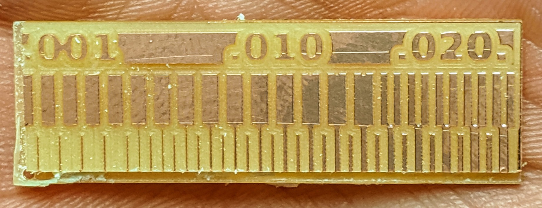
From this, we can see that the mill refuses to try and mill gaps smaller than about 0.015 inches, which matches up well with the 0.0156 inch width of the 1/64 inch end mill.
We can also see that it appears that the smallest reliable trace between two gutters is about 0.006 inches wide (but see below).
We also measured the outside dimension to ensure that this lined up as expected. We were confused until we realized that the original .png file had a double-width line specifying the outer rectangle. It is not clear to me why .png seems to be preferred over .svg for milling.

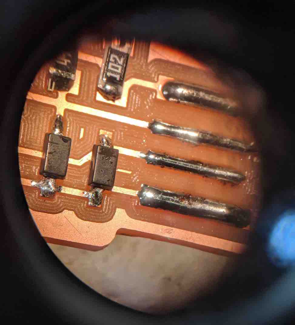
We also took a look at the test pattern result with a high power microscope. Here's the screenshot that Zach took. It's neat to be able to see the full detail with which the copper metail is deformed by the end mill, and also the trace of the end mill in the gutters.

From this view, I'd actually be much more comfortable with saying that the minimum trace between two gutters is more like 0.008 or even 0.009 inches, instead of the 0.006 from the less magnified view above.
To mill my Brian Board, I first set up to mill a clean board. I set up
for 4 offset passes, but in retrospect would have preferred to use 5.
The first problem I had was that I had written down "move to lower right corner"
to establish the origin, but this didn't look right to me -- I thought this would
try to mill off of the edge, and risk breaking the end mill. After some thought
I deceided to try moving the origin point to more like the top left, and this
did indeed turn out to be correct. (Whew.)
I ended up milling two boards, because I had never surface mount soldered before and was worried I would wreck my first board.

I found a couple of youtube videos and watched them about surface mount soldering. I then practiced a couple of times on a scrap PCB board. This was helpful. I found that for my old-man eyes, it was critical to use the magnifiers, as well as to have some way to hold the board steady. Flux definitely helped. I went with the following approach:
This sounds easy enough, but it took me some real practice with the tweezers to figure out how to move things slowly enough and to keep the parts from jumping around like little fleas.
Eventually, I got enough courage to try a real board. The first three pieces took a lot of time, after that things went pretty quick.
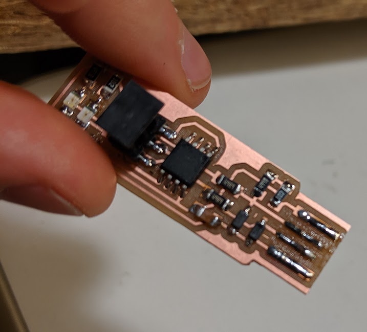
Fortunately, my board was functional on the first try. The only issue was that my USB connection was a little loose, so I went back to add more solder there to make the ridges even higher.
This worked well.
I followed all the steps, including blowing the fuses and confirming that the board still worked. However, I wasn't able to use the board to program another board, as I didn't have a second programmable board available.