Before going further, I'd like share the
sipstool I have come across in MacOS. It is really handy for resizing images in bulk from the commandline. Here is an example usage:
sips --resampleHeight 500 -s format jpeg -s formatOptions 30 *.jpg --out resized
Here, resized is a directory in which all of the matching .jpg files will be output as resized images.
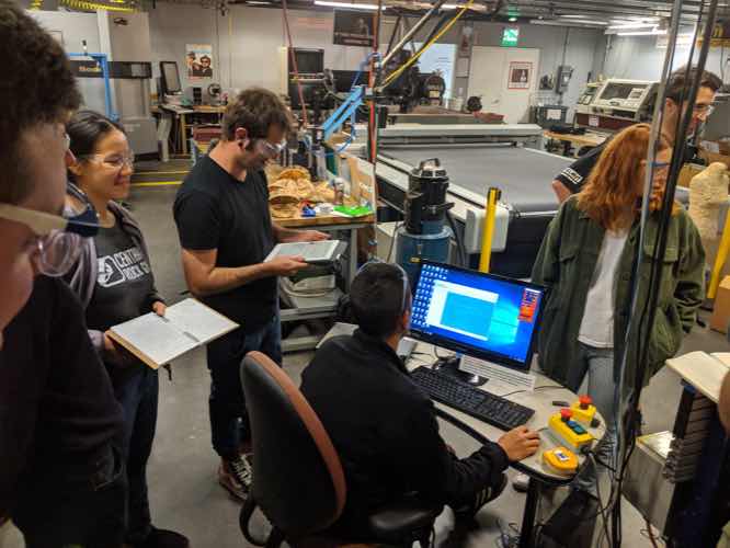
We had a large group working to characterize the ShopBot. Given the large number of folks and the limited amount of hours (since scheduling was tight -- there was a lot of demand for the machine) we just did a few simple tests.
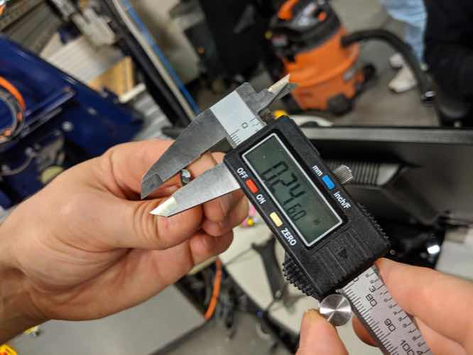
We cut out a circle to test the difference between the specified diameter and the actual (measured) diameter. The difference turned out to be smaller in reality by about 0.03in. This was consistent across two other test pieces as well.

Interestingly, the end mill itself was also smaller than the advertised 0.25in, by about 0.01in or so. This means that there was a fair bit of broadening due to wobble, etc.
We also tested out some thin strips to see how thin the ODF could be cut and still retain reasonable strength. Based on stories, we had expected that 1in wide pieces would fall apart, but this actually was not the case. The 2in pieces were totally fine. That being said, our apparatus involved flexing them hard manually, so there was room to be more precise there.
I am planning to make a Foucault Pendulum for my final project, with an end effector that can apply paint (or maybe ink) so as to be able to make low resolution representational paintings. The idea here is to be as minimimalistic as possible, but still get a reasonable 3 axis machine. Using the Earth's rotation allows us to get one axis for free, and a second axis is provided by the linear motion of the pendulum.
One of the design considerations is that the pendulum itself should have a relatively long period, so that the velocity across the work surface on each pass does not end up being too fast to do usefully precise work. The obvious solution here is to make the pendulum very tall, but there are diminishing returns here pretty quickly. For example, a 4m pendulum has a period of about 4s, but a 10m pendulum has a period of 6s -- only 2s more, despite it being quite a bit harder to find a spot for. I spent a lot of time this week trying to think of various ways to slow a pendulum down, with the most useful thoughts involving flywheels. (Camron also helpfully suggested finding weaker gravity...)
An additional consideration is that it would be nice to keep the end effector square to the work surface. So my current design uses parallel pendulum arms for this.
My overall initial design was tried to max out the size I could achieve using two 4x8 foot sheets of 3/4 inch plywood. This turned out not to be a good idea. When Zach heard the dimensions I was talking about for the top connector piece, he suggested that we do a test run to make sure we didn't get too close to the edges -- keeping in mind the experience from another student with and endmill hitting a screw.
We ran a test with a Sharpie pen stuck into the ShopBot, using a 1/2in collet, so we could see exactly where the cuts would go. The test showed that, indeed, the piece hadn't given enough margins, so I needed to re-design for smaller pieces.

The next available time slot for me was Wendesday morning. My redesign is in place now, made easier by having everything parameterized (although there was still a little bit of residual fitting needed for FreeCAD.) I will try to get this in and done in time for class.


I ended up spending my time Wendesday morning getting blocked by various VCarve issues, mostly around duplicate vectors and open vectors. This was confusing to me, in part because VCarve makes it difficult to identify.
Joao and Camron both helped me look at these files in Rhino, which seemed like it would provide a way to help join up the open vectors. But this was not successful for my files, despite many attempts.
Debugging this, I think that what happened was that I exported my files from FreeCAD using Flattened SVG from drawing, straight from 3D objects. It looks like this didn't take the top surface, but instead projected both the top and bottom lines (and also the zero dimension vertical lines) down to 2D, obviously overlapping but in some cases becoming impossible to select from other tools. It looks like the right way is to first create a Shape2DView from the Draft workbench, which I will try next.
Also, adding fillets in VCarve looks like a waste of time on the limited ShopBot schedule, so I went back to add those interior T-Bone and DogBone fillets in FreeCAD. This will have to wait until after class today or on Friday to finish, which is dissapointing.