Week 10: Networking and Communications
Board 1 - ESP8266 AT Only
For this week's assignment I decided to experiment with both ESP boards. I am mostly interested in WiFi communication (not a big fan of Bluetooth) and using the ESP boards as nodes to a central server for both retrieving real time data and for being pushed data via sockets. My original intention was to create a device that can run in promiscuious mode and scan the WiFi for devices trying to connect.
For this I decided to start with the ESP8266 and based on Neil's example create a new design and include two LEDs that I could use as a sign of life
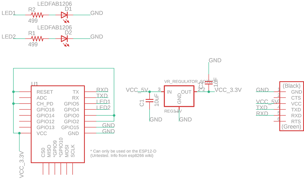
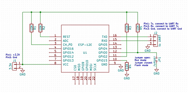
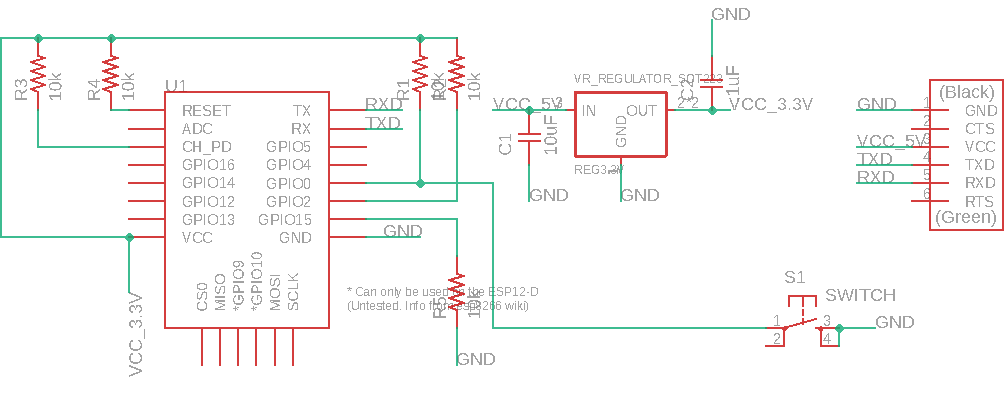
I designed my board in Eagle, and used a width size of 12 for my traces and used a ground plane. Below is my schematic for the board.
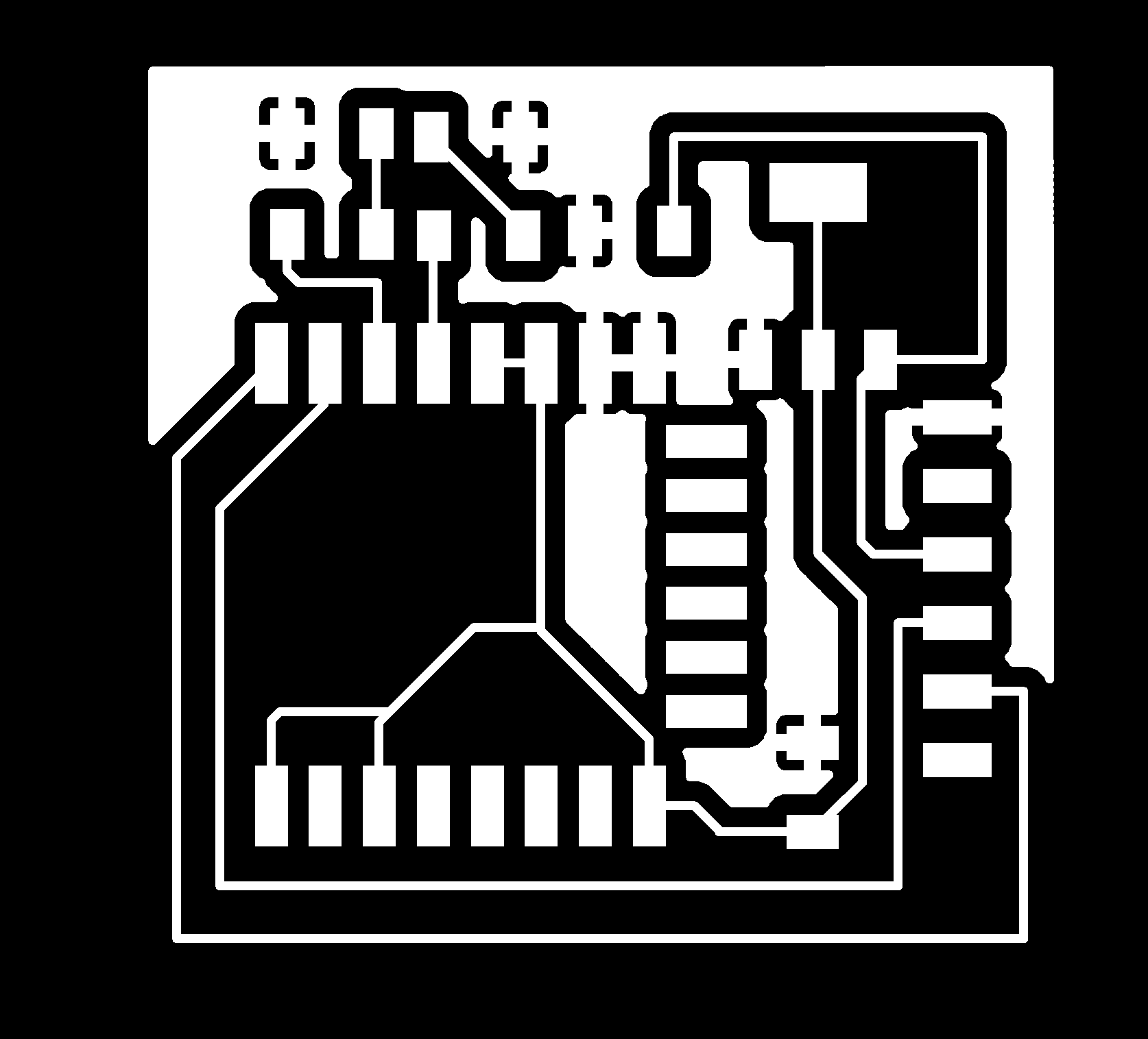
After designing the board I exported the file as a PNG and used mods to mill the board. I positioned the LEDs at the top and had no problem to do all traces in one layer. On the left image you see my components and on the right the traces to eacch one.
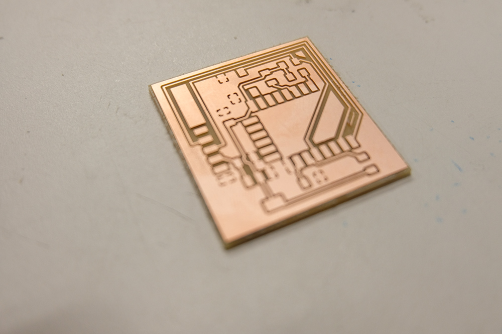
I used the Roland SRM20 to mill the board and had it done with no issues.The board milled and I was able to start stuffing the components (I actually took documentation of the board straight off the mill but my camera exposure was incorrect and due to me not checking I ended up with photos that were pitch black).
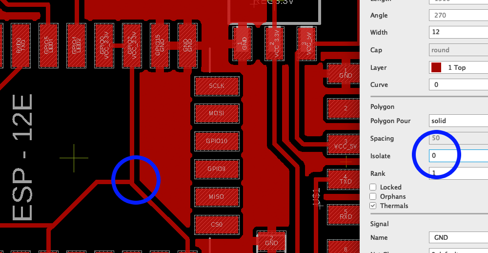
I then went to to populate the board with the components. Here is were I ran into trouble. I noticed that some traces of the board were joined shorting VCC to GND. I checked my design file and in the view on mods and didn't see the problem there, but what I noticed was that my setting for the ground plane had a isolate value set to 0 (zero). And even though on mods there wasn't a joined trace it did come out on the board.
Learning #1 check your board prior to stuffing
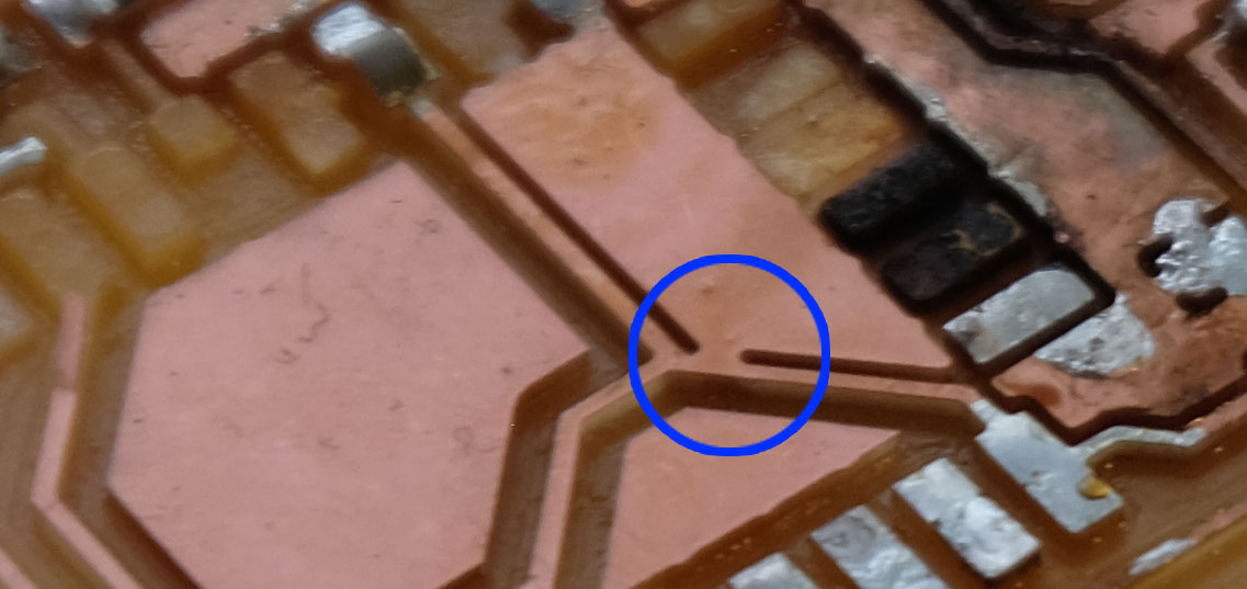
The larger issue was this trace was under the ES8266 and I couldn't really find it other than just checking that the board was shorted by the multimeter. After a huge effort of desoldering the ESP8266 and it's pins using a combination of braiding and heat gun I lost the confidence the ESP was alive - even the PCB board got burned in the effort
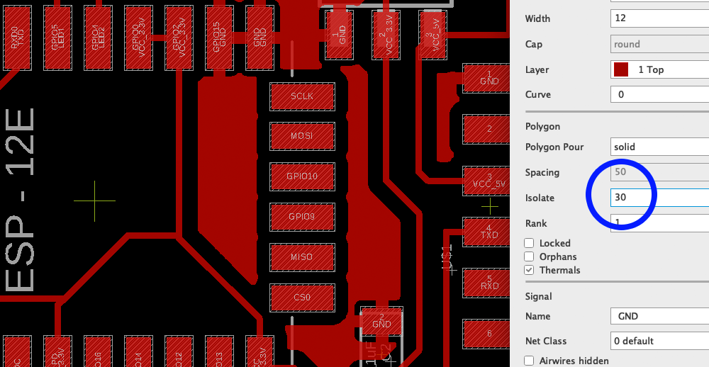
To prevent this issue I changed the isolate value on Eagle to give a much larger distance between the ground place and the traces. The image below shows my initial distance, where the issue was and the short on the fated board.
A huge learning from this was - ALWAYS CHECK THE BOARD TRACES UNDER THE MICROSCOPE BEFORE SOLDERING, EVEN IF IT LOOKS BEAUTIFUL AND SHARP THERE MIGHT BE SHORTS IN THE BOARD. Below is a value that safely distances the traces from the ground plane and minimizes the odd of an issue
After a trip to Porter Sq. to get a new ESP8266 module from Neil (thanks Neil!) I returned to the lab and did the soldering carefully and stuffed my board
Learning #2 Check your FTDI voltage prior to programming
To program the board I used miniterm on Python and the AT interface. But at first when connecting the board and opening the serial connection at 115200 I could just see gibberish coming out of the board to the serial terminal
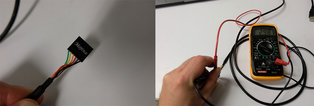
By doing some inspection I found that the FTDI cable I was using (a cheap knock off) was actually giving me 3.3V voltages from the USB output - the USB spec is set to 5V, so 3.3V after going to the regulator I was getting an inconsistent 2.4V. Important to remeber the regulator needs headroom so if the regulator is a stepdown to 3.3V it expects a voltage higher than 3.3V to function properly
In summary, the regulator was underpowering the ESP8266 causing it to malfunction. My quick solution to this was to swap the cables for another FTDI and measure the voltage, and when I saw 5V on the output that meant the cable was OK to be used and my board worked.
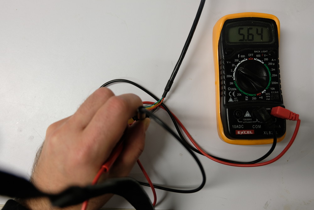
Now testing with a good FTDI cable you can see the 5V volts ouput, the regulator steps it down to 3.3V and the board works.
Programming the Board
After these hurdles I managed to get the board programmed and could access the AT interface. Below you see me issuing a few commands to check the firmware version and listing the available networks
A few handy commands for programming the board is to use the pyserial list ports (to see where the board is connected) and miniterm:
python -m serial.tools.list_ports python -m serial.tools.miniterm /dev/cu.usbserial-AK06RLV0 115200A few AT commands I used
Just sign of life check: ATReset the board: AT+RST
Get the version: AT+GMR
List access points: AT+CWLAP
Join access point: AT+CWJAP="MIT"
AT+CIFSR
I am still not very happy with my result as I just made the board work, for next week I will pursue my demo of making a sniffing device with the ESP8266 that can fetch the AP broacast packets and display them in the serial terminal.
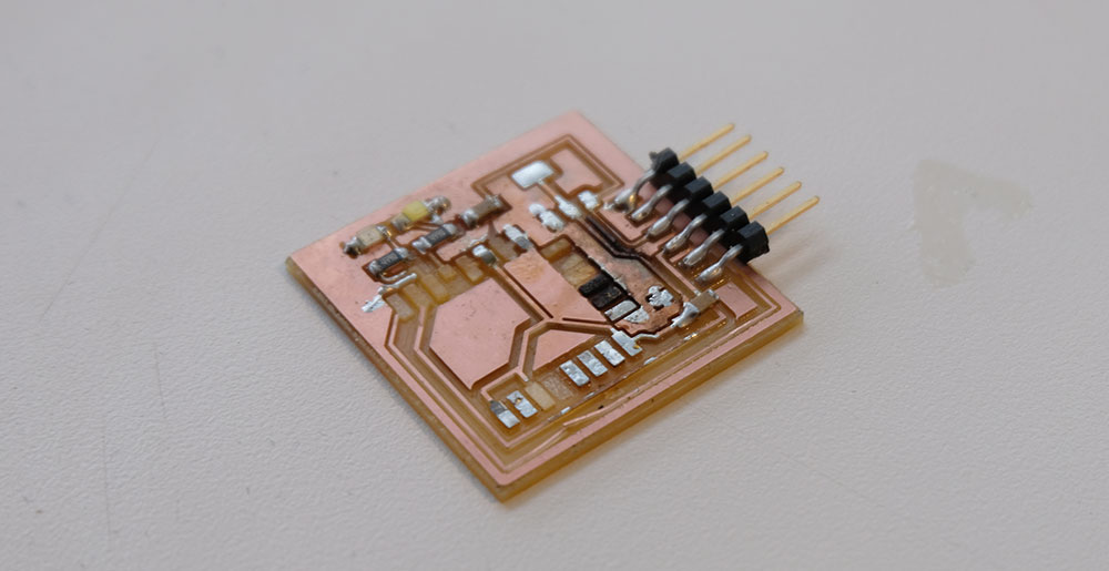
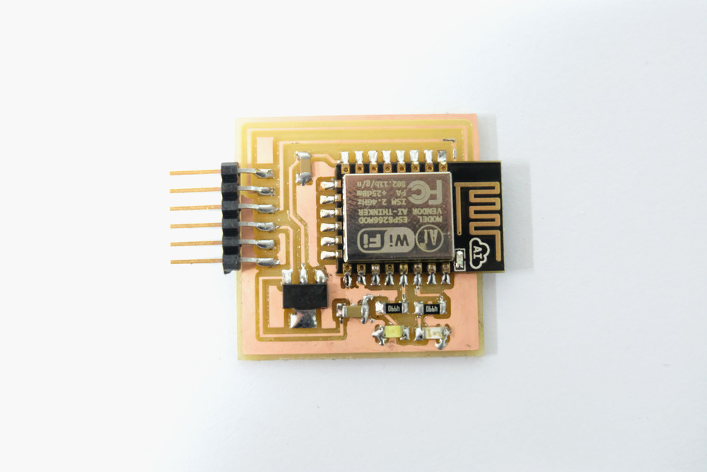
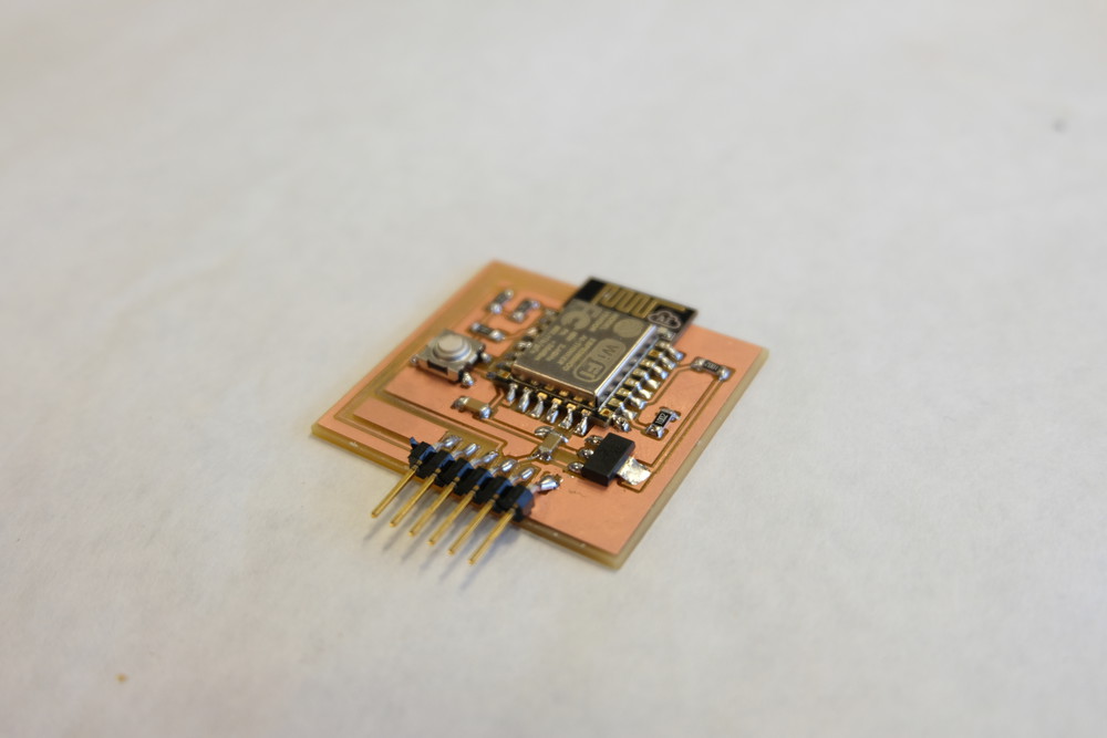
Here's an image of my final board.
Here is a video of my programming my board to become an access point
Board 2 - ESP8266 Internet Sniffer
After I spent some time with the ESP8266 I decided to push for a more complete application and build a WiFi Sniffer that can operate in promiscuous mode and watch the traffic as devices probe access points.
One of the limitations of my previous board was that it could only work in AT mode so I couldn't flash any other programs on it. So in order to make it flashable I found a good tutorial in this wiki
This board connects the GPIO0 to a switch that can pull the resistor to GND making the board be in Flash mode. So I redesigned my board based on this new design.
Below is the board layout and traces for milling.
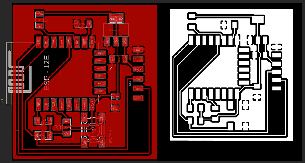
I had no issues with the milling and ended up with very clean traces on the board surface. I then moved on to stuff the board with components.
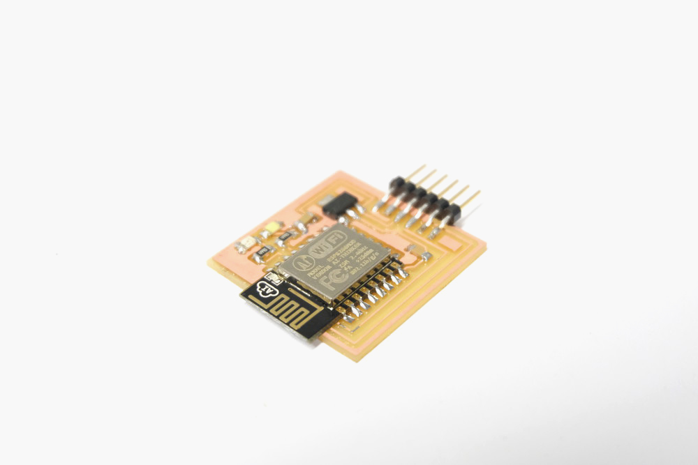
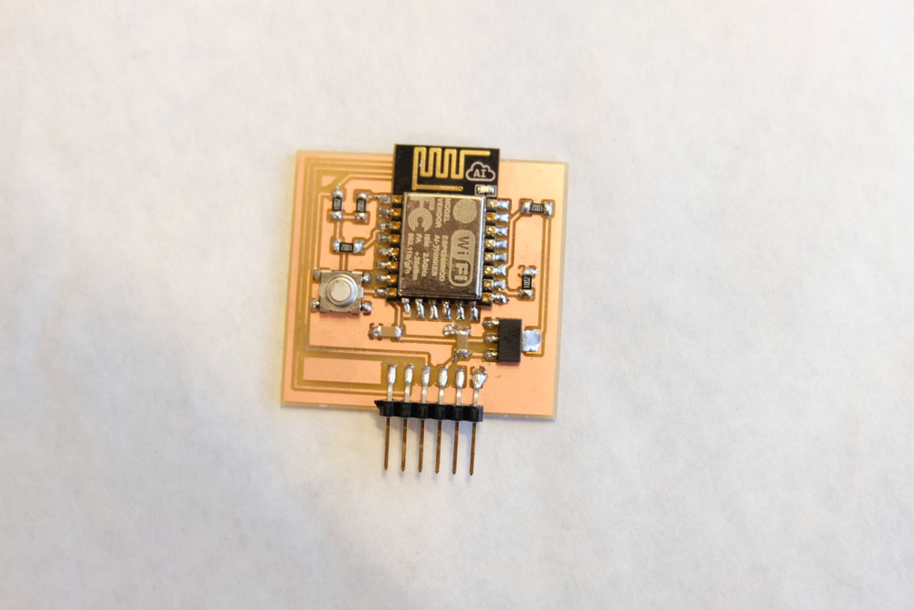
Here is a final image of the final board populated with components and ready to be flashed. To enter Flash mode just press the button and upload.
I decided to use the Mini Sniff from Hackaster.Prior to uploading the code to the board you have to make sure that the you have the board added to your board manager. That the serial speed is correct on both the Serial print of the library and the board you are using.
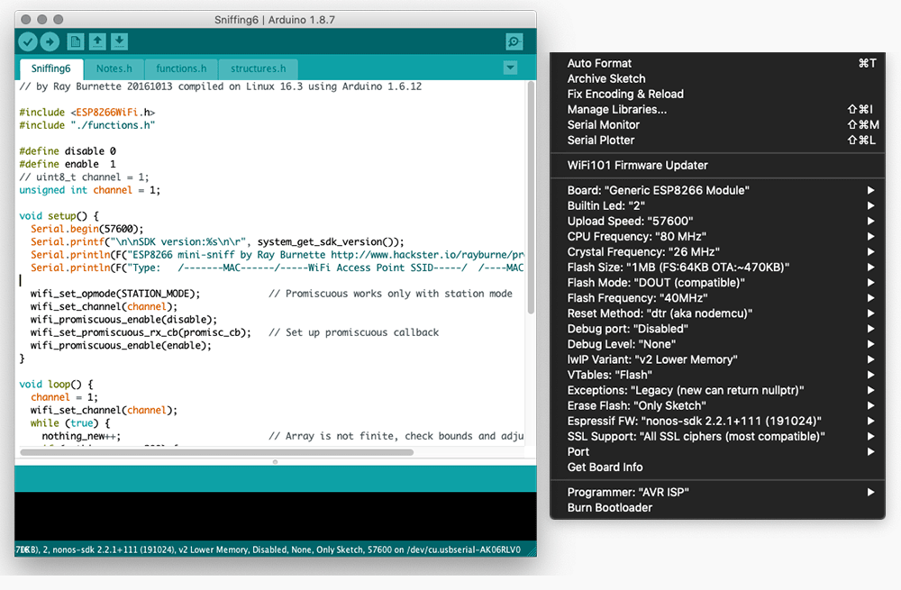
Above are the settings that I used to program the board. After doing those steps just then compile and upload. The program should sucessifully load on to the board. To view the result of the sniffing in action. Use miniterm
python -m serial.tools.miniterm /dev/cu.usbserial-AK06RLV0 115200
Below is an image of the board powered up and sending data to the Mac via serial listing all APs and nodes trying to connect. It works!