Week 2: Electronics Production
For this week our task was to characterize the machine in terms of which drill bit size and features we are able to get with that drill. mill and load firmware on a programmer ATTiny85 based programmer board. For this assignment we were required to mill a board using a PCB milling machine (either the Roland SRM-20 or the Modela 10X). After milling the board we had to solder the surface mount components on to the board and program it using a AVRDude programmer.
Characterizing SRM-20
To characterize the SRM-20 mill we used a test file provided by the TAs and used a 1/64 end mill on the machine. In the characterization process we also learned how to move the machine head to specific x,y,z position and zero the machine. One useful trick I learned was to hold the drill bit down when using the hex key in the screw that holds the drill bit. In this way you are sure that the drill bit is really touching the plane.
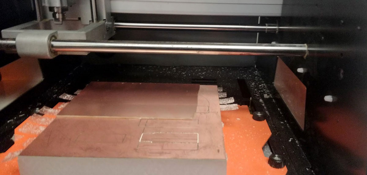
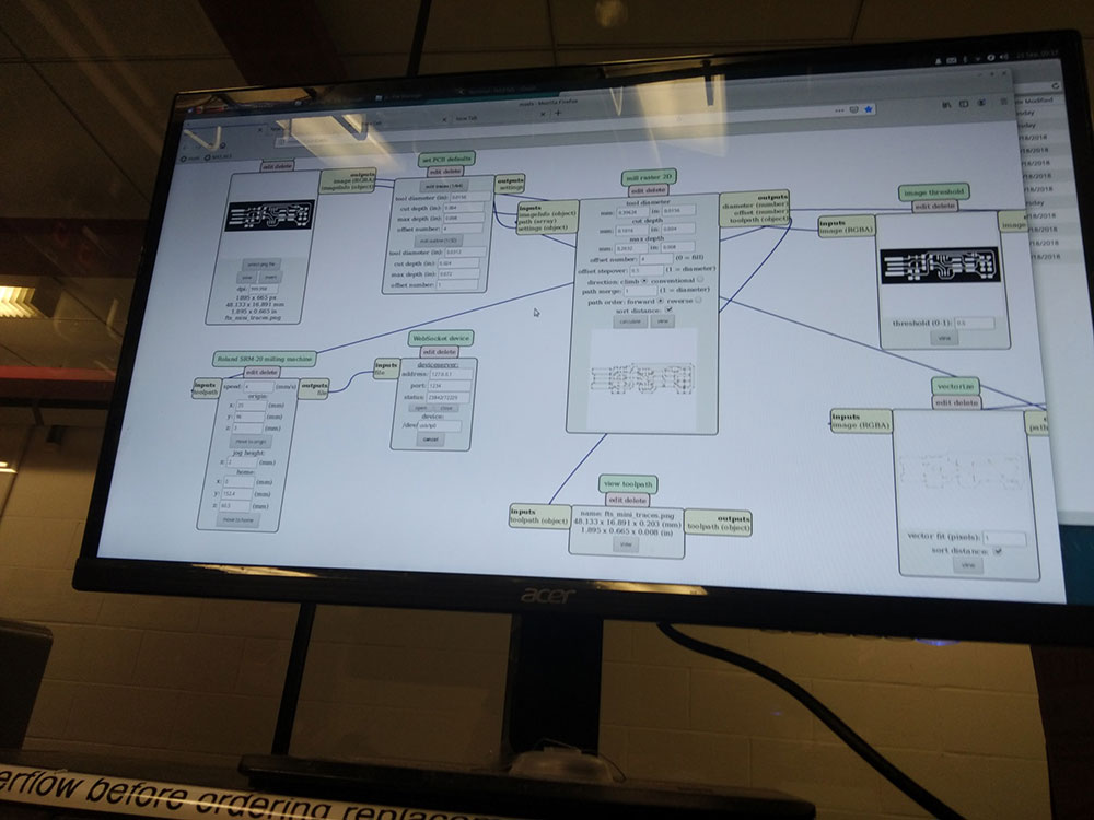
I first loaded the board on to the machine and used the mods flow to load in the PNG of the test file with the different feature sizes.
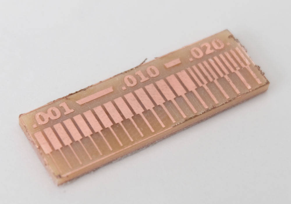
In this step I used the 1/64 mill with the test file provided. I ran the mods software with two modes, one using 4 offsets and another running 6 offsets. With this I settled on the 4 offsets as my default for milling the board. This step was also important to learn a few tricks regarding a how to zero the drill bit and best way to attacch the copper board to the milling machine. I had some experience with PCB milling before so this step wasn't very difficult for me to accomplish. I also wrote a guide for the Modela some time ago that can be useful for students to use.
Milling Board
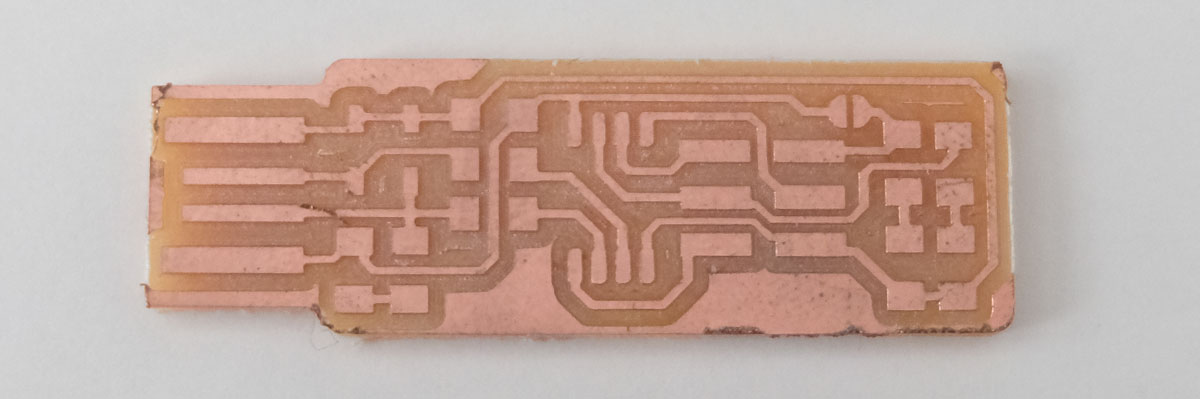
I then loaded the design file provided, and using the 1/64 mill I started milling my board.One good sign the milling is happening according to plan is to check the chips that come out from the copper. If the chips are too small that means the drill is not going deep enough to cut the copper. If the chips are too large it means the drill is going beyond the copper thickness and actually milling the substrate itself.
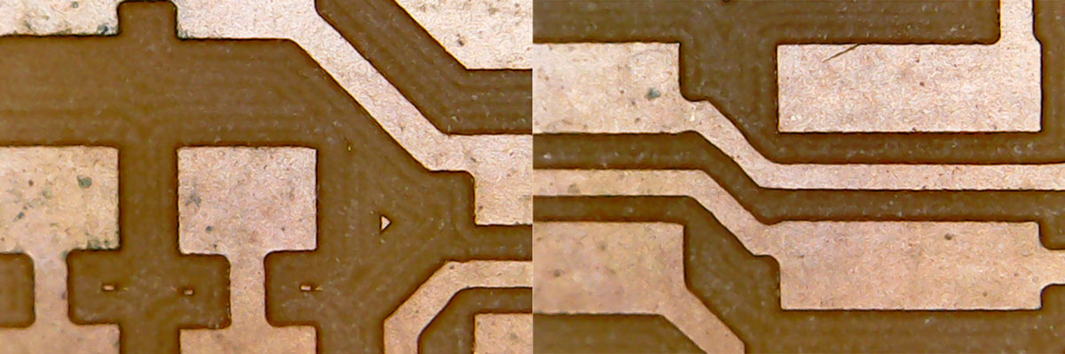
After milling the board I did some inspection to see if all the traces were crisp and clear and to check if there were no traces that could be damaged or came off the board. In the image below you can see the traces are healthy and have very sharp corners which is a good sign. I used a table USB microscope to make this inspection.Here is an image of the board milled with no components on:
Soldering Board
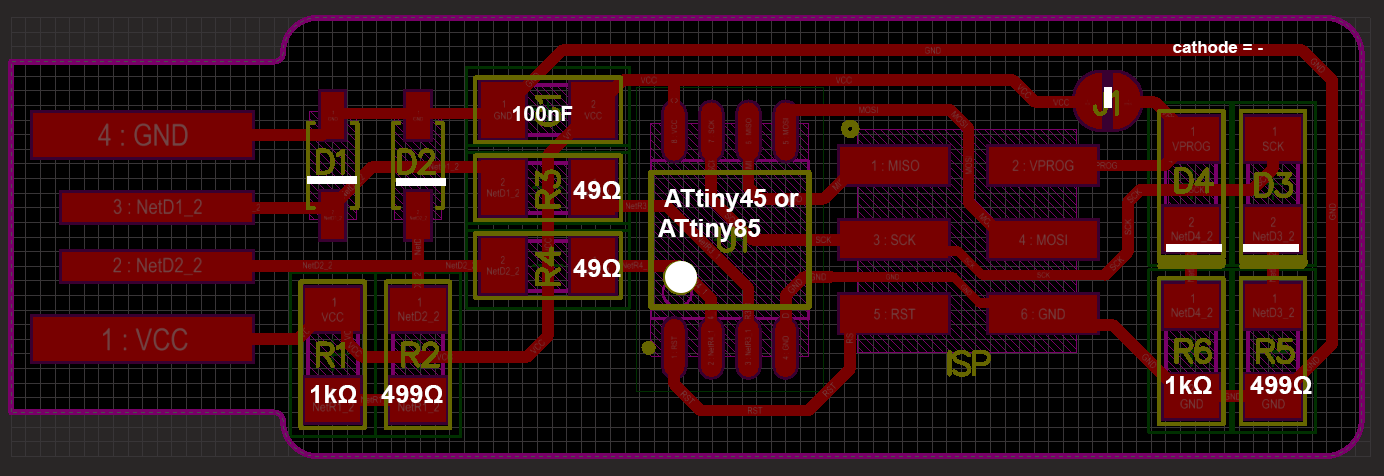
rior to solder the board I made a plan of which components should be in which places using the cheatsheet below. This helps minimize errors in resistors values. This map is a mix of the component values and orientation in the schematic and the board design. Note that I also added the orientation of the ATTiny and the diodes. This can be useful as you can solder based on component values.
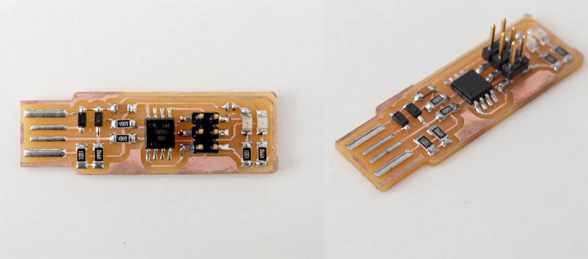
I had no major issues in soldering the board. So this is what it looks like. To have a backup I made two versions of it. Here is a top and a side view of one of the boards.
Programming Board
I followed Brian Mayton's guide for programming the board using the AVRISP2 programmer (the programmer with the large blue enclosure). I had an issue to program the board using a Macbook Pro with USB-C ports. The AVRDude programmer wasn't recognized by the USB. I suspect it might be due to the ports being USB3.0 or by any other microprocessor present in the USB adaptors that might not be recognizing the AVRDude device.
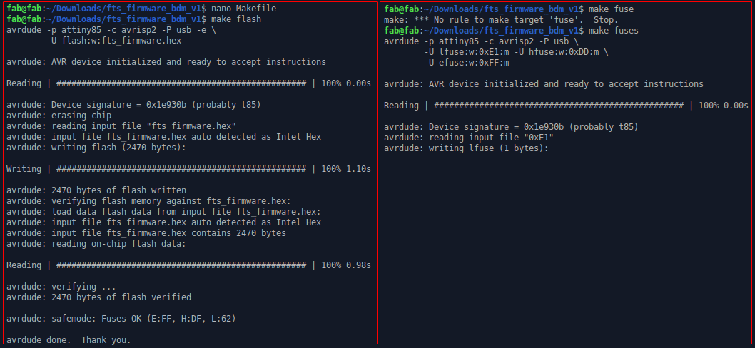
My workaround this issue was to use the Linux machine in the lab to download and compile the firmware. And using the AVR Dude on the USB ports of the computer I could get the program to compile and program the board.
Testing the Programmer
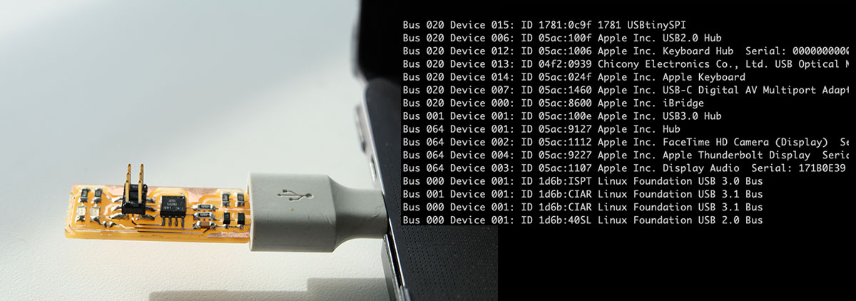 After programming the board I used the soldering iron to remove the connected solder jumper and now I can see the board as a USBtinySPI on my mac.