Week 5: Computer-controlled machining
In this week's assignment our task was to train how to use the ShopBot CNC machine, characterize it and then design and build something big.Files:
Characterization
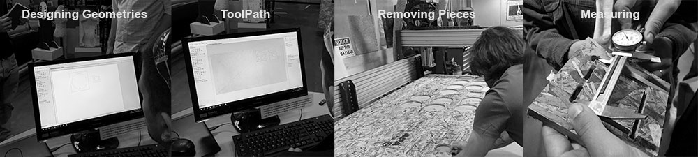
For the characterization of the Shopbot we designed a series of geometric shapes to define the offset between the designed geometry and the CNC cut part. For this process we followed the steps of: (1) designing a circle and 3 rectangles on VCarve (2) Generating the toolpath (3) Removing the cut parts and comparing the designed geometry vs. the CNC cut result.
Settings
Cut type: Conventional CutStart depth: 0.0in / Cut depth: 0.55 in
Cutting: Edit Select Cutting Tool
Tool: Wood 1/4 downcut 57-910 2 flutes
Tool Diameter: 0.25in
Pass depth: 0.125in
10000 rotations (spindle rate)
Feed rate: 120.00 inch per minute
Plunge rate: 60 inch per minute
Passes: 2
Results
For our first set of results the 4" diameter circle geometry was measured at 3.9725" demonstrating a 0.0275" offset between the designed geometry and the result (image left).For the outside square the expected size of 5" resulted in 4.95" a 0.05" offset.
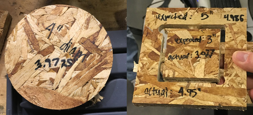
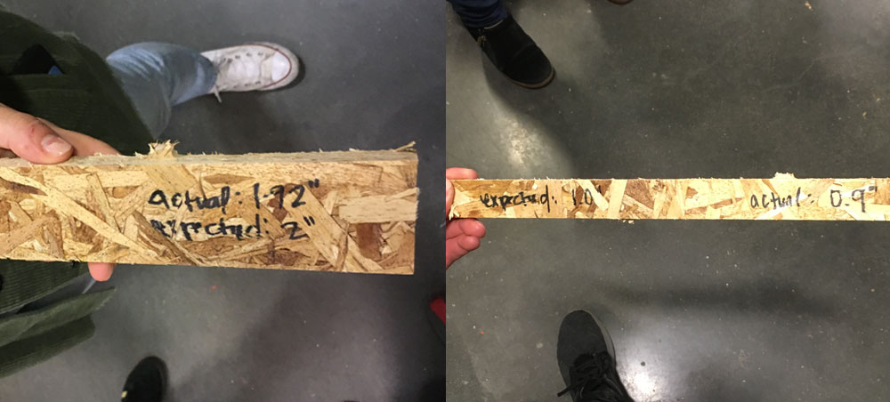
On the two rectangles the expected measurements deviaded respectively 0.08" (left image) and 0.1" (right image). This deviation can amount to approximately 0.02" average offset between the expected and the result.
Making Something Big(ish)
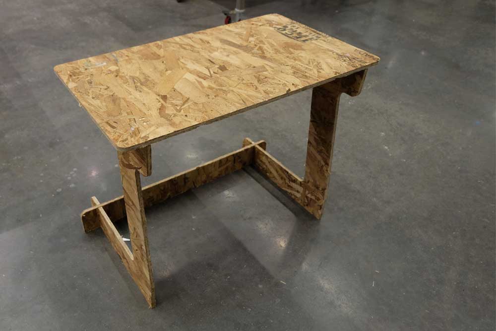
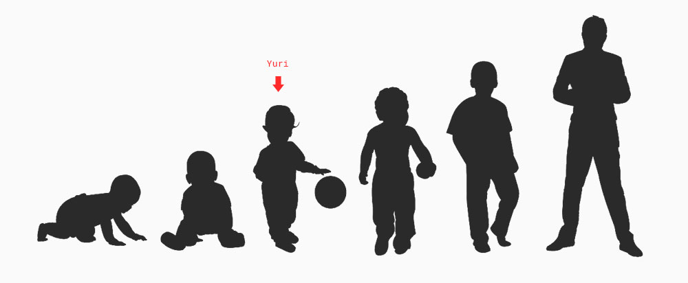
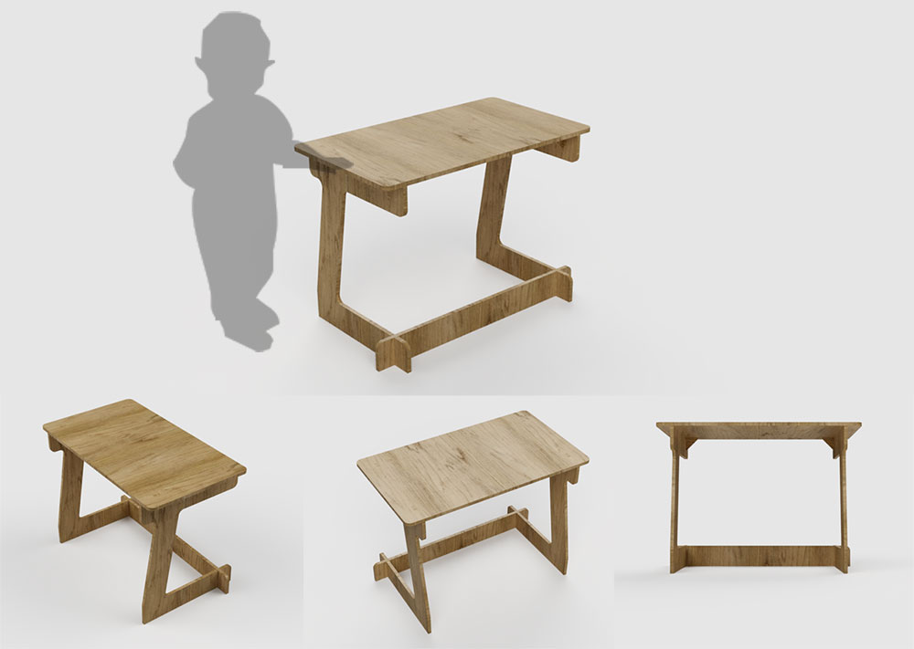
For this week our task was to make something BIG. Rather than making something big I decided to make something that could grow. I have a 15 month old son Yuri that is starting to like painting, drawing so I decided to make him a snap fit desk out of CNC cut parts.
The idea is a desk that can follow him throughout his lifetime. I like the idea that combining parametric models + digital fabrication I could create one design that can be tweaked and refabricated every couple of years.

Now with 15 months I researched online and found that that a 55cm tall desk with a 70cm top length would be good enough for his height. By making the design parametric I could then change the dimensions as he grows older.
Designing the Desk
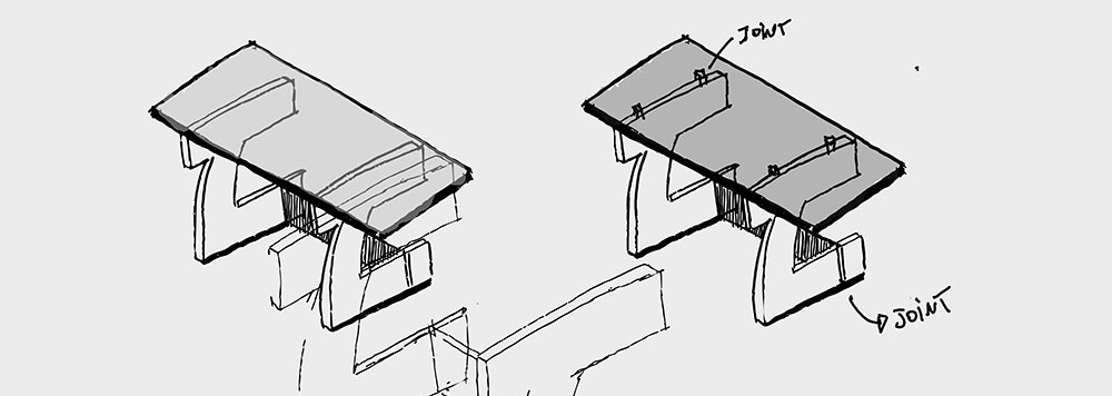
I first sketched a few ideas of snap fit desks, looking at references online most of desks comprised of 2 independent legs connected by a beam at the bottom and the top. I decided to use this as my base design and experiment with different beam lenghts, fillets and curvatures. Below are some of my early sketches.
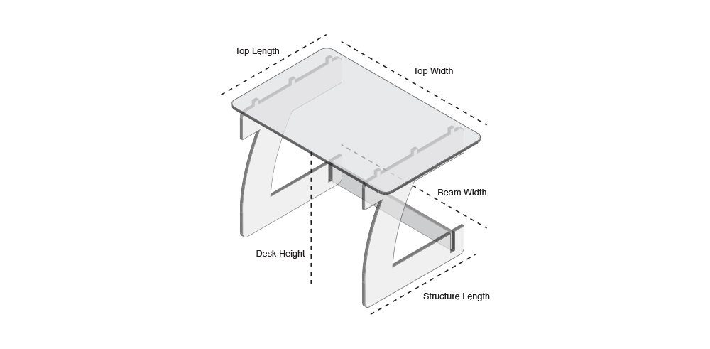
 I then moved into using Adobe Illustrator to make a diagram of my parts. This wasn't to any specific dimension but more to get a feel for the different parts and for me to define a strategy for my parameters. The variables I think that could change with his age are the desk height, structure length (as the height varies) the length of the top and the length of the beam that connects both legs.
I then settled into this design and decided to move to modeling this in Fusion360. I have some experience with Fusion but this time I wanted to experiment and really parameterize my design.
Although this seemed like a good idea it actually started getting on the way to have so many parameters. The most important ones were the parameters to define the desk height, top (width and length), structural beam (length) and material thickness - given that my plan was to prototype in cardobard first before moving to the CNC cutter.
The geometry with most constraints was the leg as I had to constrain both the bottom and top beams and vary the height and angle of the connecting beam. I also fixed the kerfs (that attach the legs to the top of the desk) so I could change the kerf size without changing their position.
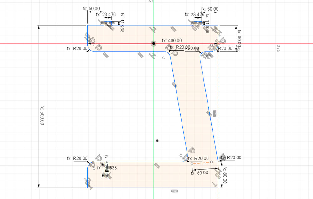
Once I got the constraints to work well I could then change the height of the table and dimensions on the table top and the design would adapt to my new dimensions. I realized that having too many of the other dimensions as parameters didn't really help. So for next time I will try to use less parameters and more constraints to make it easier to explore.
One other learning was how much detail should I add to the sketch vs. in the volumetric domain (thanks Zach F. for the tip). I added fillets and other details to my sketch and I started running into limitations of what the Fusion360 sketch domain could offer - for example I couldn't do boolean operations. Zach's suggestion was ideal: sketch the very primary forms using sketches, move to the volumetric domain by extruding the shapes as I saw necessary and then create sketches from the faces.
After spending some time on the modelling I got the dimensions that worked for his age and I produced some renders to see what it would look like. I was happy with the overall design, the balance of the beams and the overall look and feel.
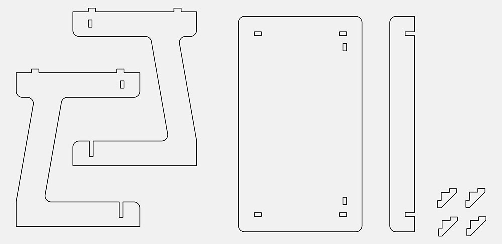
After a few rounds of design and iteration I was happy with the result. I then exported a DXF for the sketch of each component. The top, two legs, bottom supporting beam and two triangles that hold the top in place.
Prototyping My Design
The layout below has all necessary parts to assemble the desk. I choose to use simple joints and create two kerfs on each structure that slot into the desk top and an interlocking beam that connects both legs together from the bottom.
Following Alfonso and Zach's suggestion I also added a supporting triangle to the top at the end of the beam to make the desk more stable. The image below shows all the parts. (I added a pair of extra holding triangles).
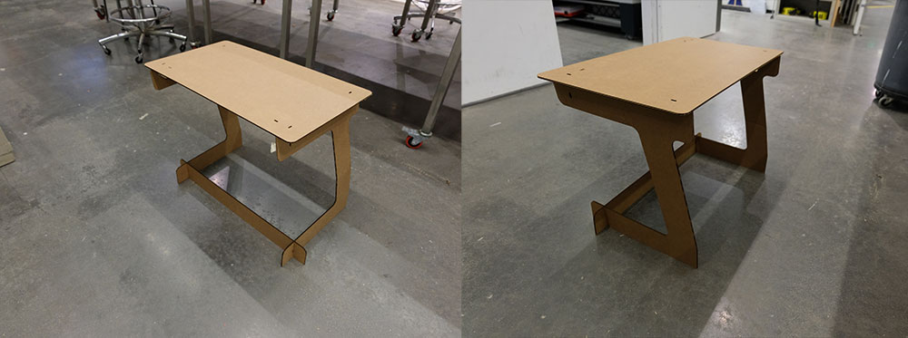
I then proceeded to prototype this in the laser cutter. Due to the first size of the desk I could do a 1:1 prototype out of cardboard. I changed the material thickness to 4.317mm and procedded to laser cut the part.
For the laser cut prototype I used a 0.2mm offset each join. I decided to make the holes 0.2mm larger (looser fit) that I could then fix with glue than to have to sand the board.
After a few rounds of iterations on defining kerf sizes and tweaking some dimensions I was satisfied with my first prototypes. Given the fact it used cardboard the desk felt flimsy and I believe this is due to the cardboard. My expectation is that using the OSB board will increase it's sturdiness. so I locked down my design and exported the final layout files to be CNC cut in the ShopBot.
Working with the Shopbot
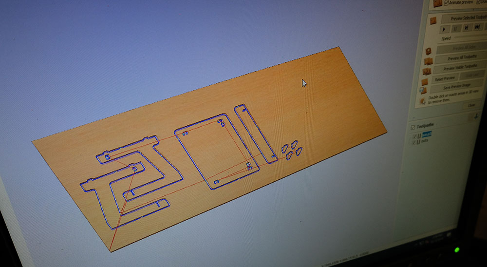
The ShopBot was really busy on Tuesday and given packup of delays on other projects I lost my slot. So what I did to make things faster was to use the smaller ShopBot computer to use VCarve to create my tool path.
I found that the process has many steps (and settings that can go wrong), to help me navigate this I created a guide with each settings.
Based on this guide I created my toolpath using two steps, one to cut and remove the internal parts by cutting inside and a second toolpath to remove the larger shapes by cutting outside. For my job I decided to use the DownCutter 1/4" endmill with the same settings as the characterization.
 After doing the toolpath and CNC ccutting the parts I put together the desk and all joints worked pretty well. The desk seem to be flimsy if pushed from the sides. So I added a metal hinge on each side of the bottom beam to help with stability.