Learning to mill
Testing the mill and finding good settings
When we went to the training for the mill, we learned that the bed of the mill is not level. This could be rectified (in the short term) in a couple of ways: by increasing the number of passes the mill makes, or by physically compensating for the slight unevenness by adding more double- sided tape to one side. Filippos showed us an example where one pass was insufficient to cut through the PCB blank, so we tried a different setting, where we made 4 passes with 5 offsets. This worked quite well, although some of the traces seemed a little thin, and it took a very long time to cut. I think I will try to use fewer offsets when I mill my own PCB, but leave the number of passes the same.
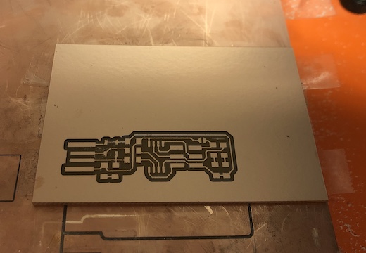
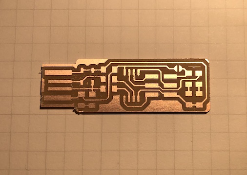
Milling my own PCB
The ideal way to spend a Sunday morning.
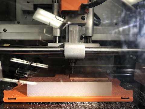
Showing up just before 10 am on a Sunday morning is great, because there's no line for the milling machine. I looked at my notes on milling settings, and decided to do 3 passes with 4 offsets. This worked fine- I was a bit nervous at first because the right side of the board didn't start cutting until the second pass, but it luckily, the endmill still went deep enough to carve away unnecessary copper. Milling the traces still took a while, but not quite as long as when we'd tried doing 5 offsets. Like before, cutting the outline was quite fast, and I ended up with a nice- looking board:
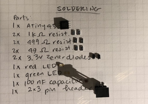
Soldering
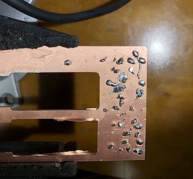
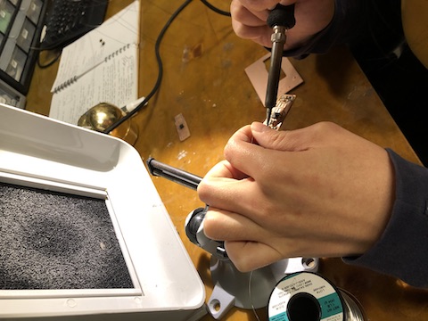
My attempt to solder for the first time!
I've never soldered anything before, so this (again) was very new to me. It was much, much harder than I'd anticipated, although some of that is apparently due to the parts being surface mounted, which I was later told is "harder" than other methods of soldering. First, I collected all of the parts I'd need and laid them out on my notebook, next to a written list of the components, so I could keep track of them. I then practiced a bit on the remains of a PCB blank, just to get a feel for how the solder flowed and how to use the iron. I found it very difficult to get the solder to stay smooth, and not to create a little peak when I lifted the solder or the iron.
Programming the board
Where everything goes wrong, I start over, and everything goes wrong again.
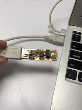
For my first board, I plugged it in to a USB cable, and got very excited when the light turned on. Looks like I got the LED colors mixed up,
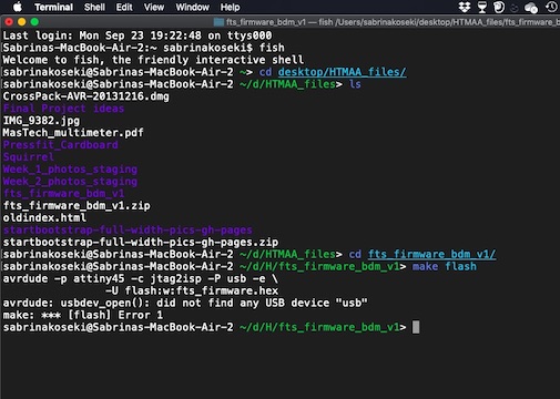
because I got a green light instead of the red light that's written in the instructions. Oh well. Unfortunately, this was the last thing that worked,
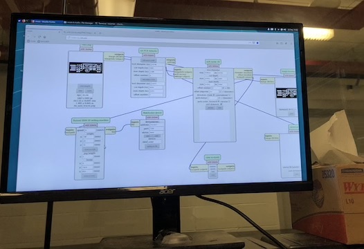
because I got to the step where I created a .hex file and could advance no further; for some reason, I kept getting an error on my terminal saying that
the computer "did not find any USB device 'USB'".
 I looked at the board, checked the soldering, reflowed some chunky solder, and, on Monday night,
asked other people check the soldering (many thanks to Eyal,
Jack, and Pranam!).
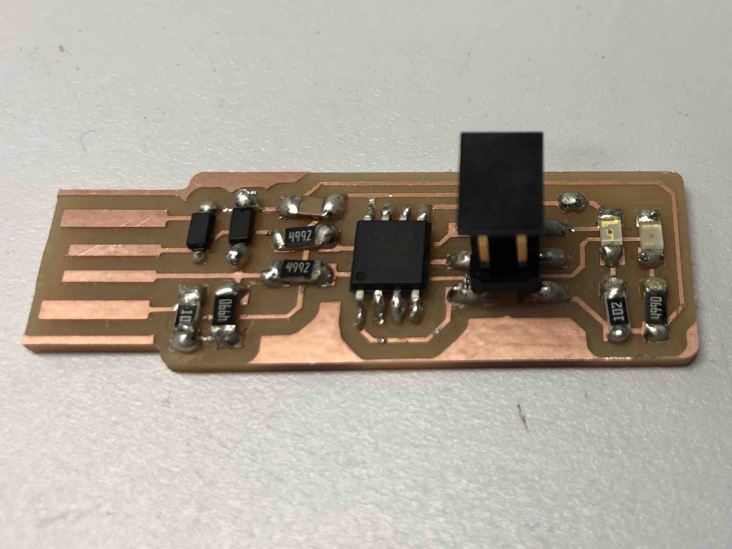
Eyal pointed out that I had mistakenly used 49.9 k resistors instead of 49.9, so I switched those out.
Unfortunately, this didn't make the error go away when I tried to program the board.
I looked at the board, checked the soldering, reflowed some chunky solder, and, on Monday night,
asked other people check the soldering (many thanks to Eyal,
Jack, and Pranam!).
Eyal pointed out that I had mistakenly used 49.9 k resistors instead of 49.9, so I switched those out.
Unfortunately, this didn't make the error go away when I tried to program the board.
Starting over!
The Long Night
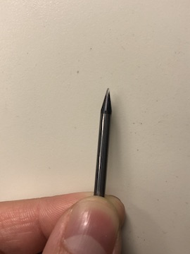
After a lot of frustration, I decided to mill a new board and start from scratch on Monday night. I also was determined not to get on the shuttle to go back to Wellesley until I got the board working and programmed, so I prepared myself for a long evening. When milling the new board, I noticed that 1/64" endmill seemed quite dull or possibly broken, but the board I milled looked usable, if a little "fuzzy", so I decided to just go with it. I then re-soldered the parts, and by 10:30 pm, I had a much neater- looking board. The solder was (mostly) smooth and shiny, and the whole process went much faster the second time. It looks like it should work!

Programming, again.
The Long Night, part II
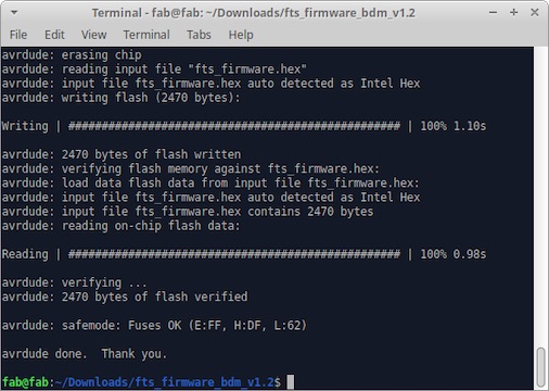
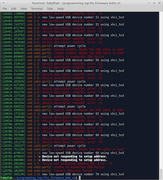
With a considerable amount of nervousness, I brought the board over to the desktop computer in E15-043 to try to program my board. I switched over to that computer from my laptop because it ran on Linux, which I hoped would be easier to program my board with. At around 10:45, I got the dreaded "make flash" command to work, which is where I got repeated error messages before. I then went through the rest of the steps to program the board and test the USB functionality. The USB connection was cranky at first, but after adding some more solder, I got it to work (I got the "new low speed USB device" message). I then blew the reset fuse with the "make rstdsibl" command and by removing the physical solder bridge on the board.