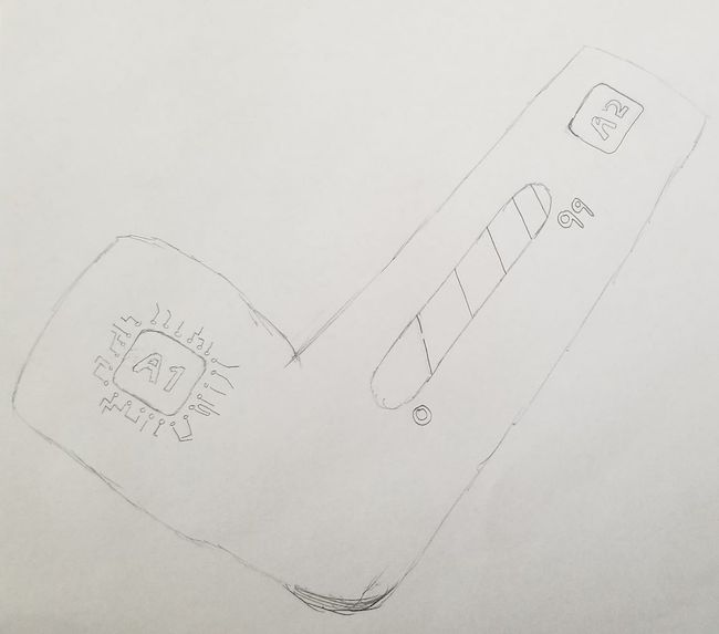
This is my first sketch of the final design I am trying to implement. I want to make a basketball sleeve that can predict your shot power and accuracy. It will tell you on an app the release time and speed, how likely it is to go in, and an LED strip on the side will show your arm charging up for the shot and the accuracy predicted. I also want it to give feedback to help aim better such as a small shock so you know when to release after data is gathered of the ideal realese angles and speeds.The first sketch is shown.
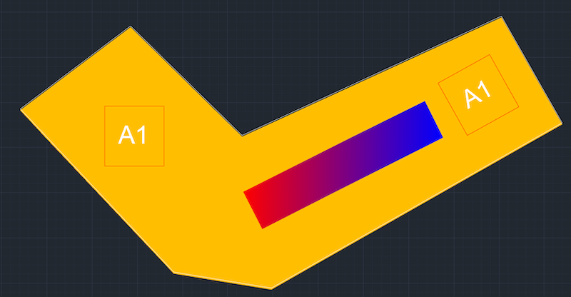
Then I tried rendering in Autocad but did not have much success. I will try another drawing app before moving to CAD to make a better version
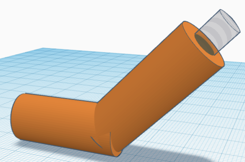
I also tried to render the sketch as a 3D model in TinkerCAD but was not able to get much going because of its limited options. This was simple two cylinders at an angle to represent an arm with a sleeve
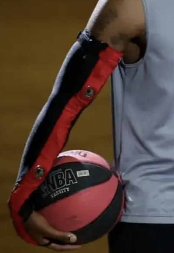
I went online and did research and only found this, but it is actually very close to what I was thinking. This is the article. My design is different but I did not know this concept existed in a prototype.
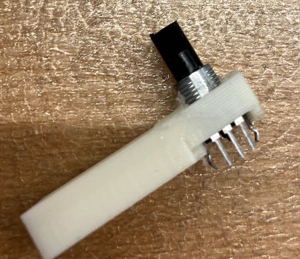
After speaking with a lab prof, I was told that a good way to measure arm angle is using a goniometer. So I decided to build my version usinf a potentiometer. Then, I can get a simplified release speed as the angular acceleration * arm length.
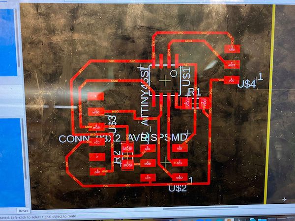
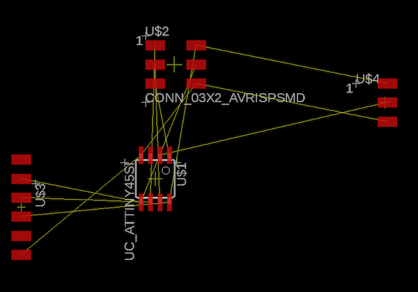
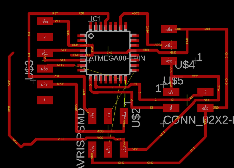
I deciced to create a potentiometer circuit to begin. I created the circuit in EAGLE using the fab library for parts. Below you can see the progress of the circuit.
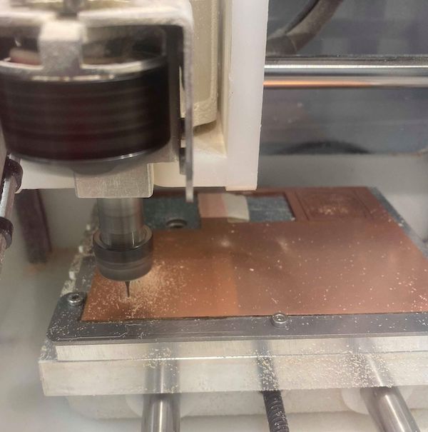
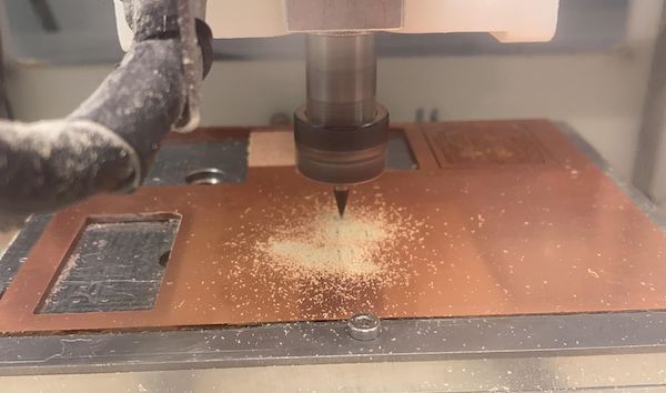
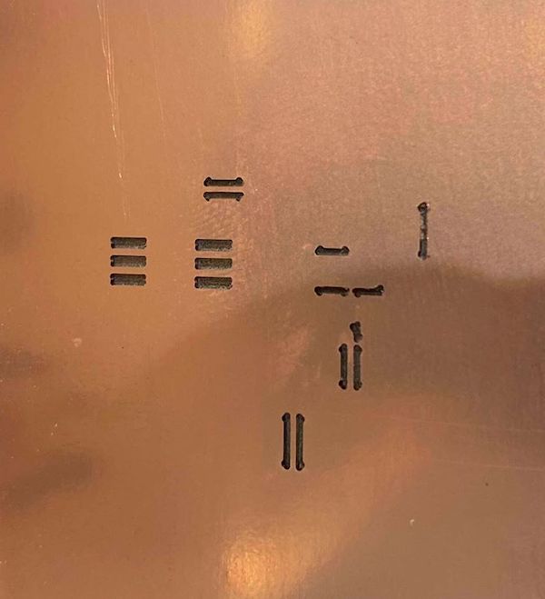
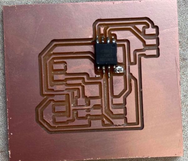
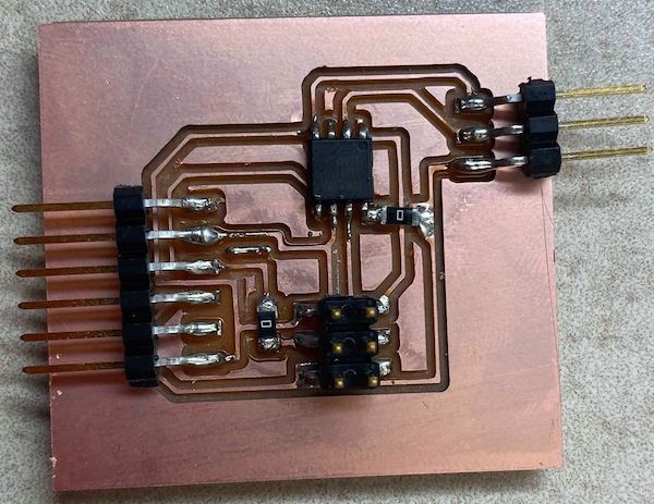

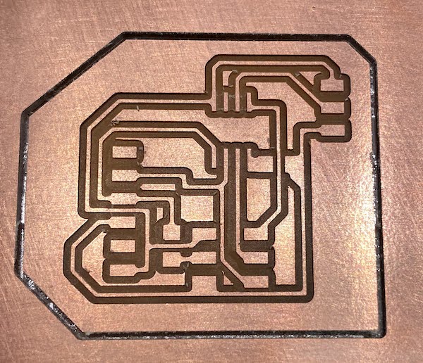
This is the milling process. First in the othermill, I used the 1/64" toolbit for the small parts. The othermill only does what it needs to do with the smaller tools and moves up sizes so that the production time is faster. After the 1/64" is the 1/32". Using this tool, the mill goes much faster as can be seen. The 1/32 cuts the remaining traces and the outline of the circuit.
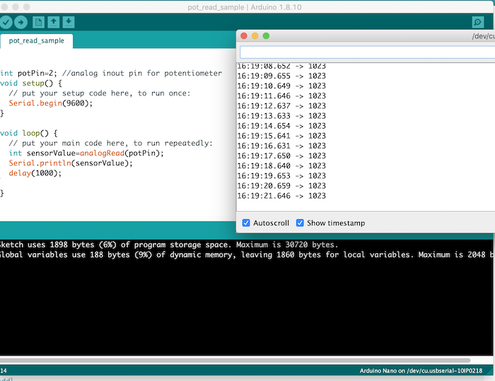
I then tested the potentiometer to get data readings. It is successfull using a 10k linear pot.
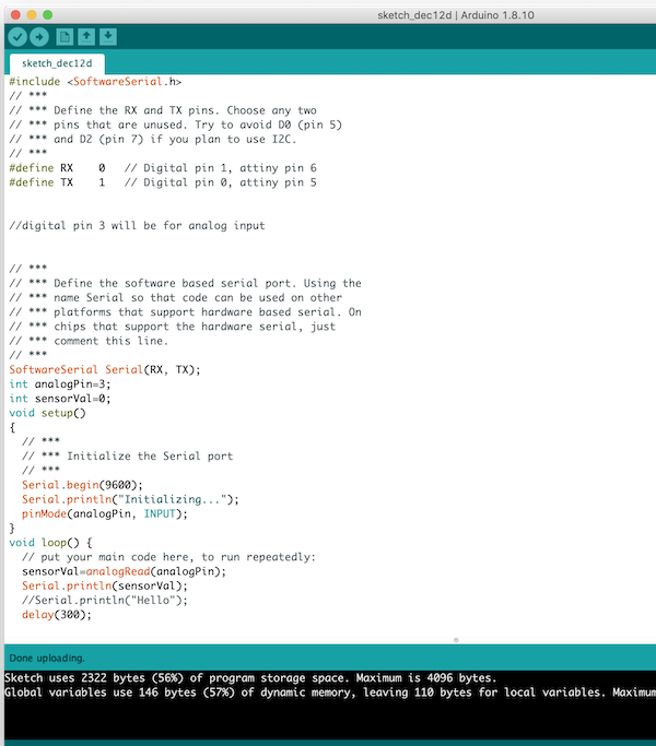
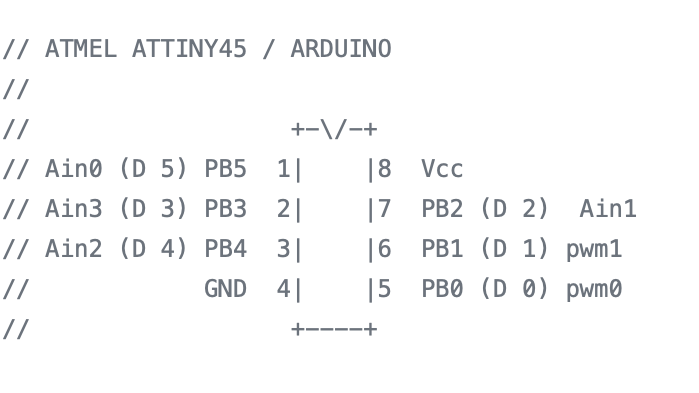
This is the code to test the pot, first using an arduino, and then using an ATTINY 45.
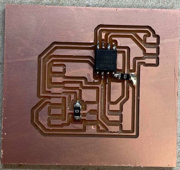
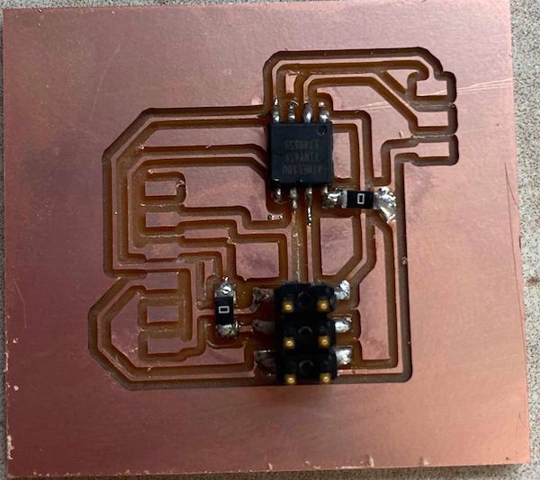
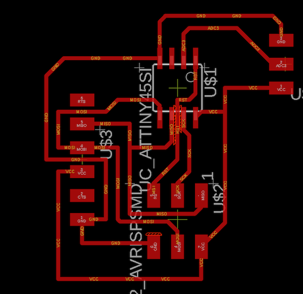
I then went back and re made the board in EAGLE. This was the second iteration.
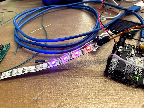
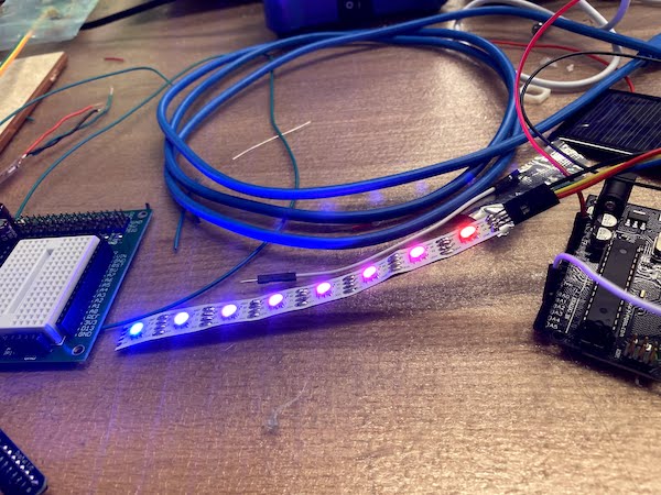
I then went on to test the LED's. I used an LED strip with CI and DI pind that are clock in and data in respectively, along with the ground and vcc pins. For the longest time I ran code using the neopixel library, but it never worked. That is until Chloe came along and told me I was using a Dotstar strip. I added the new library, ran my code, and it worked. I was using the wrong library so I would not see my code in action. I knew the LED's worked because I tested them out with a power supply and they all lit without any burnouts.
Here are the LED's lighting up as a meter.
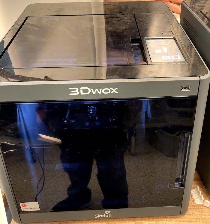
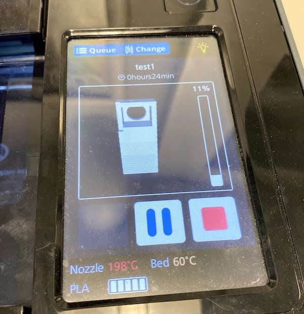
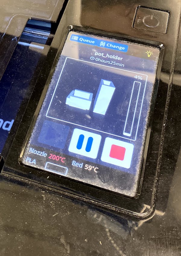
Then I went on to create the CAD parts that were required to attach to the pot and the arms. I created two parts. The rotater, which goes on the top part of the pot and moves with the forearm, and the holder, which goes on the bottom of the pot and attaches to the upper arm. I created the pieces in solidworks and printed them on both the Sindoh and the Prusa. The prusa was much faster and gave good results, so I did many more prints on it.
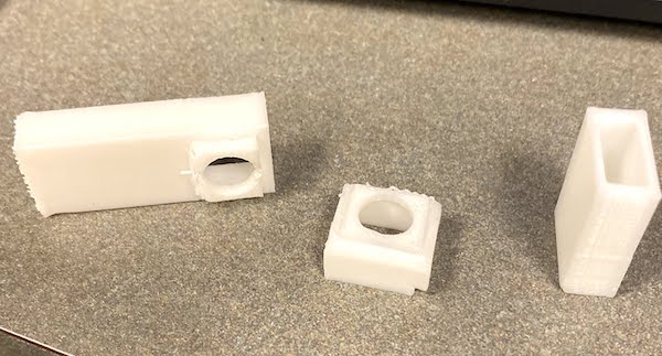
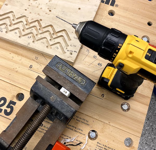
I made one of prints sidewats, with too much support material inside, so I had to clean it up a bit with the drill. It was usable but I instead reprinted in the correct orientation.
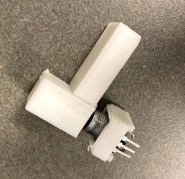
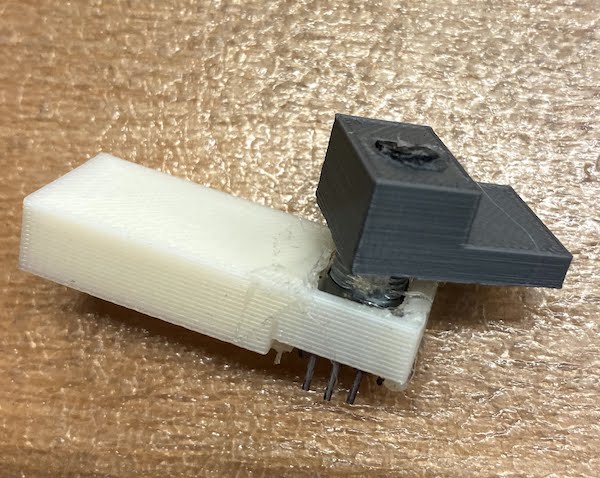
This is my second prototype of the rotater and pot holder
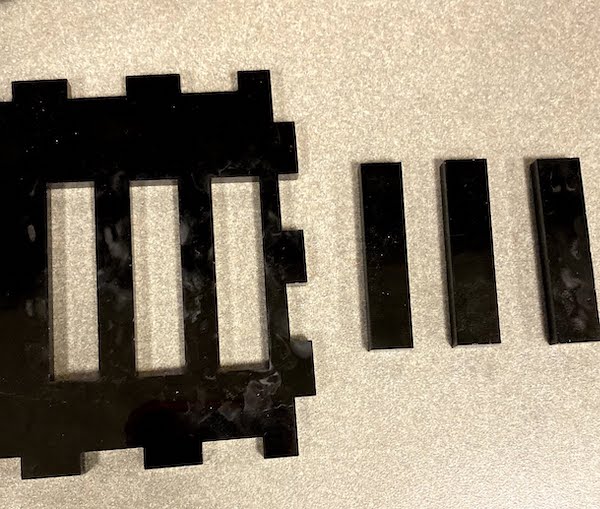
I then used the laser cutter to cut some acrylic to test the rotater for the right dimensions. The pieces were small but just long enough to test how well they would fit on the connectors.
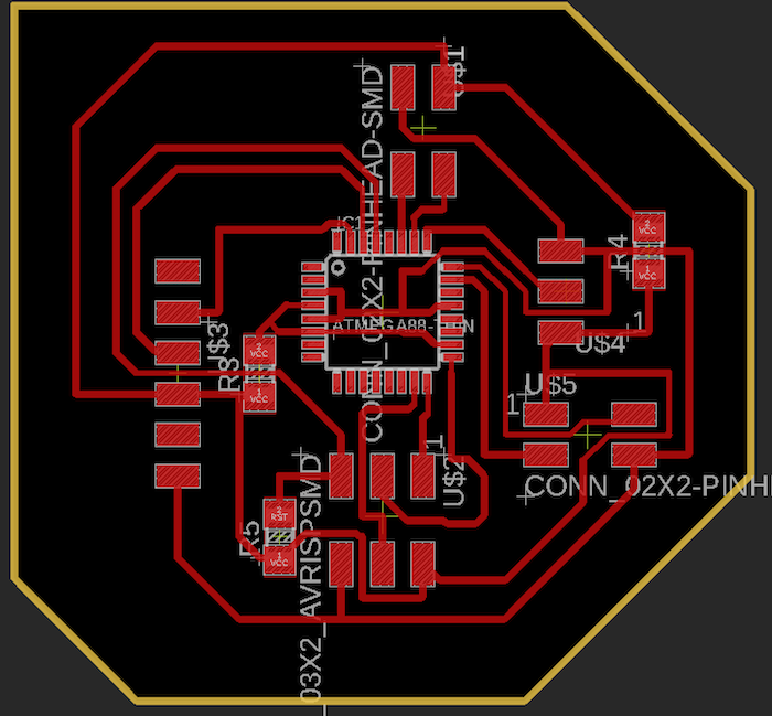
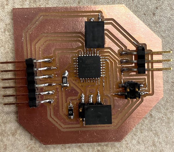
I after knowing the LED's output correctly, and the pot gave the right input, I decided to combine them onto a single board so that I only use one chip. I decided to go with the ATMEGA 329p so that I had enough storage space and enough pins to fit both the input and output devices. I created the board in Eagle once again. I was having some trouble completing all the traces, so I added some zero ohm resistors and cleaned up the board. This was my final board design.
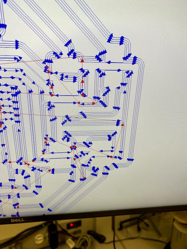
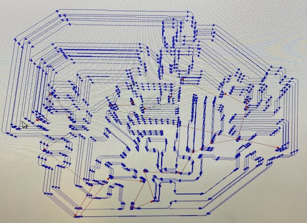
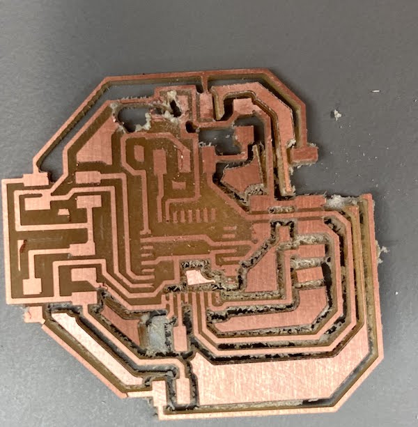
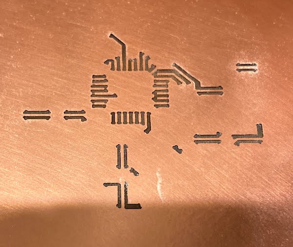
I milled the board on the Roland and the traces came out fine. The toolpath is shown. However, when I milled the outline, the machine went crazy and gave me these results. It is pretty cool but not what I expected from the roland.
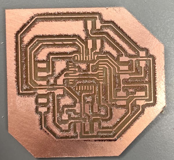
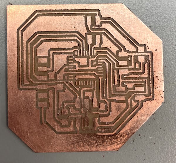
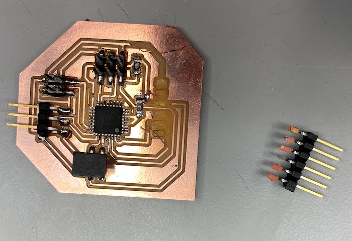
I then milled the board and it came out scratchy. But with some sandpaper, I gave it a few passovers and the results were good. It must have been the 1/32" tool since the first tool did not leave it bad.
I then realized I had an error on my board. I was shorting the connection between vcc and reset. So I could never actually reset the board. I went on to fix it using the heat gun. As I was about to test the board, I accidentaly ripped off some traces. SAD. So I had to remill and remake the board. It was great.
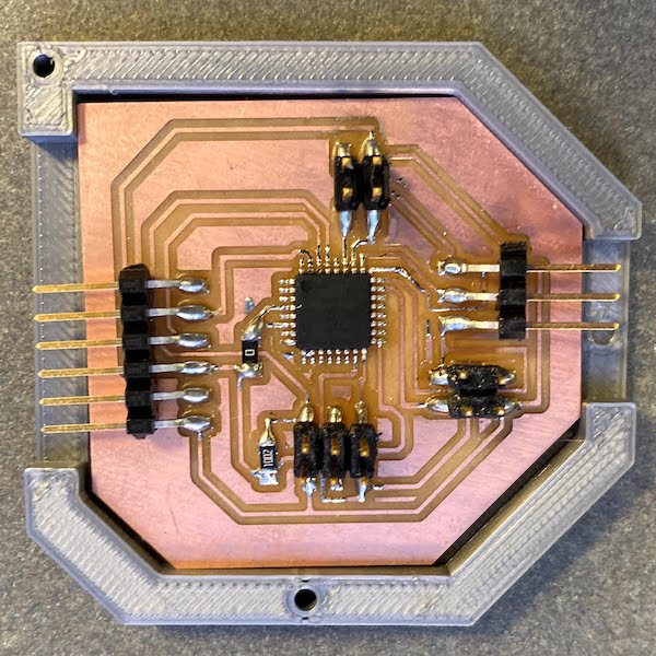
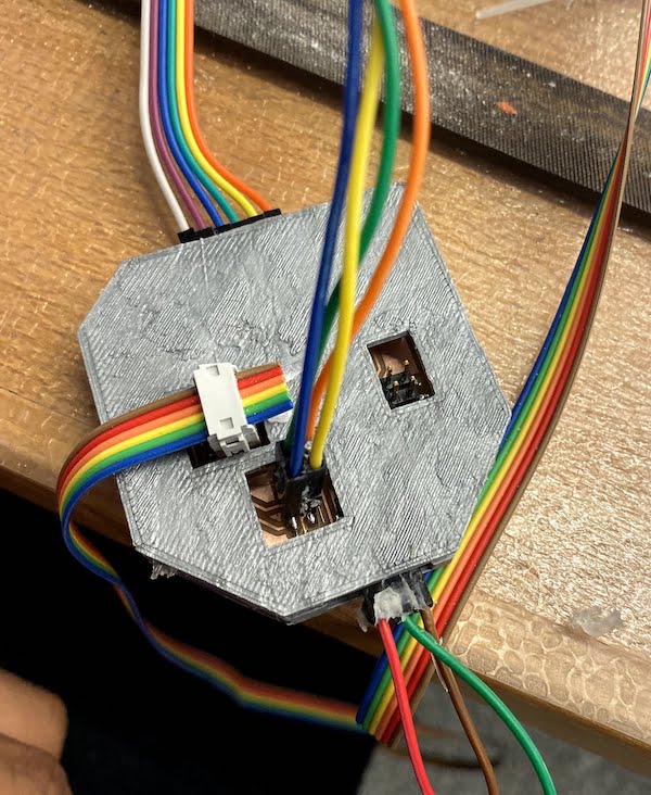
The new board is shown below with a custom 3d printed case I designed. The case fit very well with the board, giving it enough room to insert the ftdi and other cables needed.
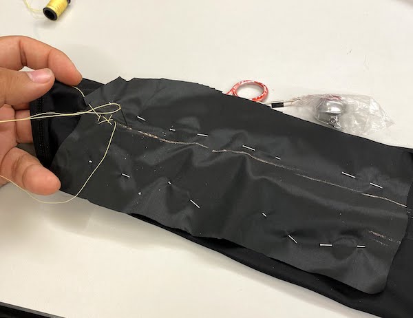
Since I did not want the arm to be too bulky, I decided to sew nylon fabric onto my sleeve so I could keep it flexible. With Alex, I learned how to do basic hand sewing techniques to get started on my sleeve. Below you can see some of the bad stiches I made. I am still learning, it was my firs time.
I used yellow material to more easily distinguish on black the path I was taking.
I then reprinted some conncetors, this time smaller and more rigid to hold in place. I again used the sindoh and the prusa.
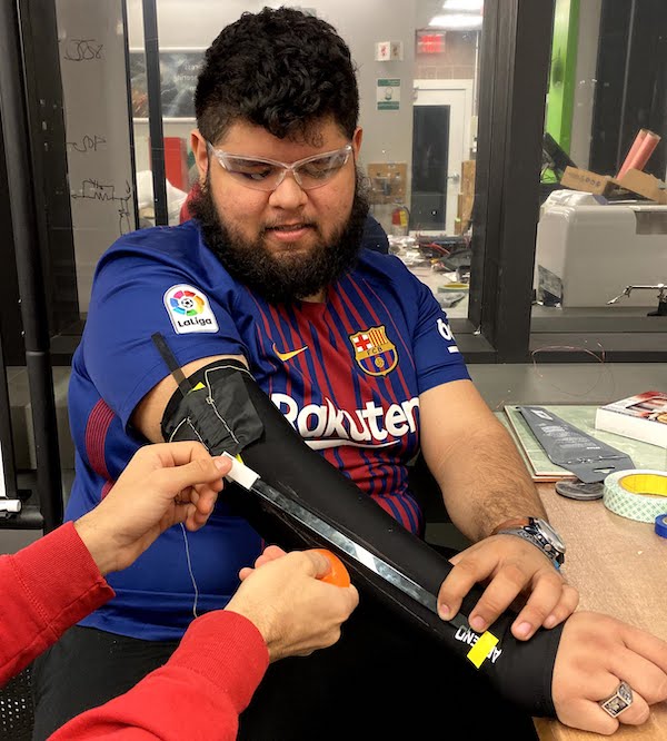
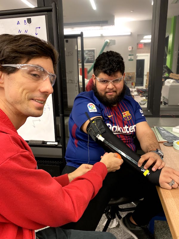
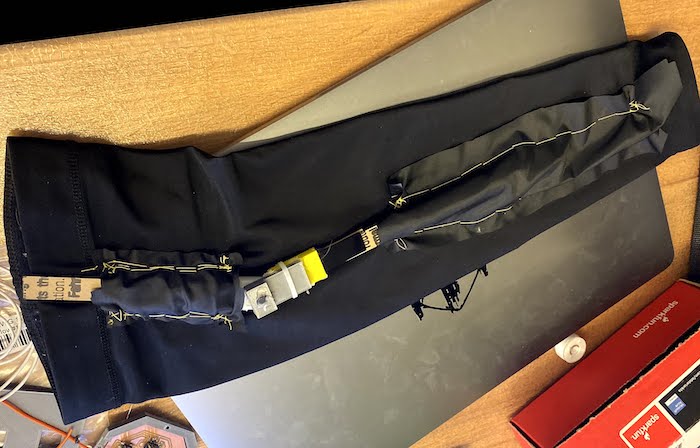
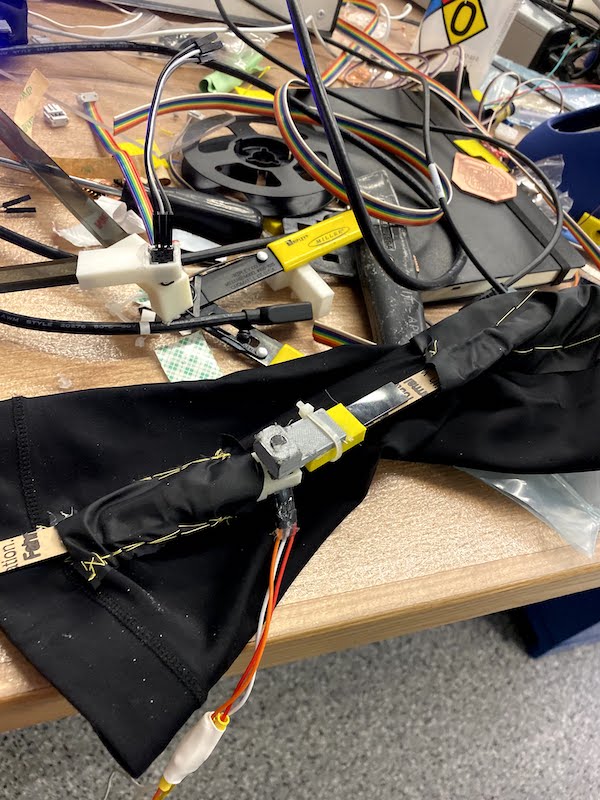
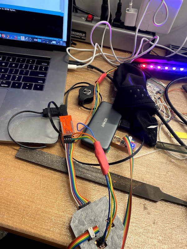
Putting it all together, this was my first working version. I need to cover it up so it does not look bad.
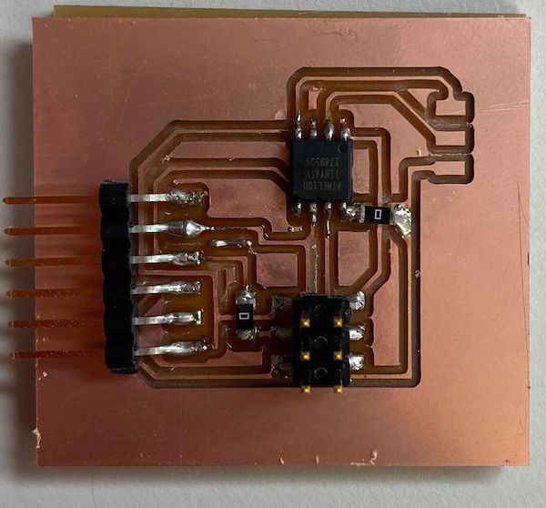
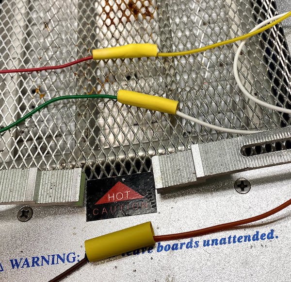
I created the wires for the board using the rainbow wire and 6 pin connector heads. I soldered some flexible wire with connector ends and used a heat gun to shrink wrap over and keep the wires more organized.
This was the wiring needed for the project.
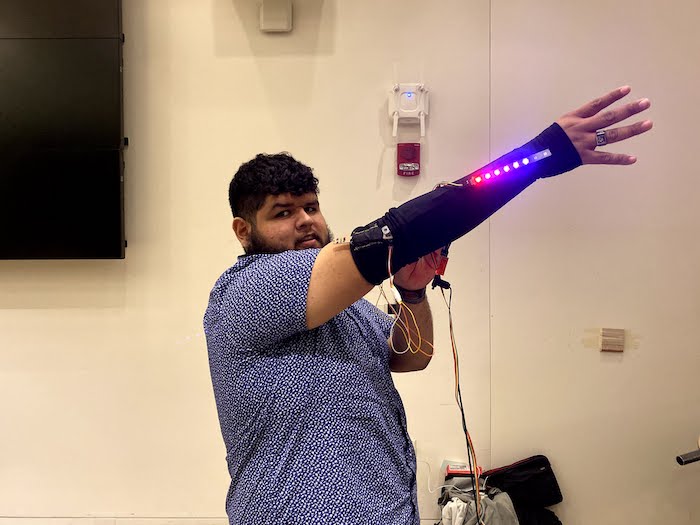
I modified the arduino code to output an arm velocity and a relase angle. This is how the demo looked showing half of the skeleton. On the left you see the underskeleton. Next you see the final testing for the outer shell. And finally you see how it looks in real life.
FINAL PRODUCTION VIDEO