The first step was finding a sheet big enough so that the board would fit. I used a copper sheet that was avaiable in the lab. Using double sided tape, I added it to the surfaces on the board directly below where the PCB would be cut, and on the perimeter to keep the copper board in place. I then taped the other side to the mill's sacrificial layer.
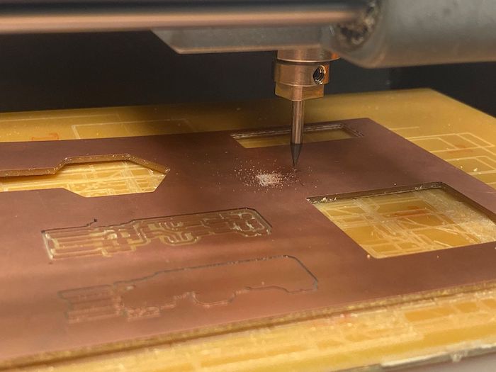
Then I "zeroed" the origin, by adjusting the x and y components to resemble where I wanted the PCB to be on my sheet using Neil's software program. I uploaded the Traces image to the program and changed the bit to a 1/64" bit to cut the traces. We typically use the 1/64" for traces and the 1/32" bit for outlines to cut the PCB from the copper board.
The first board we cut as a group was a disaster. Several bad things happened. The traces were not cut deep enough and the board had very jagged edges. So without even cutting the outine, I also accidentaly removed the copper plate from the sacrificial layer, which is bad for knowing where to begin the cut for the outline. I started over the entire milling process
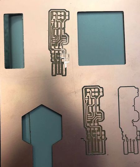
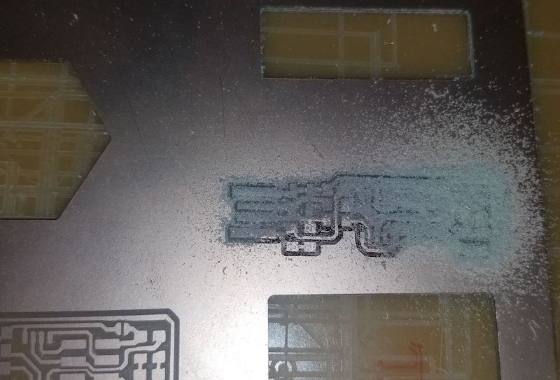
The new settings we used are shown. We changed the max depth cut to 0.006" instead of the default 0.004" so that the mill would cut deeper than the last time and ensure we had better cuts. These are the results of the new board after we cut the traces and the outline.


After finishing the board, it was time to add and solder the components to make it a programmed board first, and later a programmer. The components are described below. I used blue and red LED's in my board, but the colors are interchangeable and can even be the same, what matters is which LED lights are assigned to the different duties.
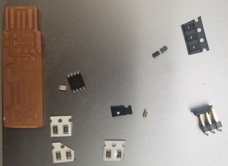
It is convenient to solder the center of the board first. That is, the ATtiny45 and the pin header. Starting form the center
and working your way out is a good tecnhique to ensure that you have enough room to add the solder. Good tools to use are the tweezers to
pick up the small components, the heat gun to remove any incorrectly soldered components, and desoldering wick to pick up what you want removed.
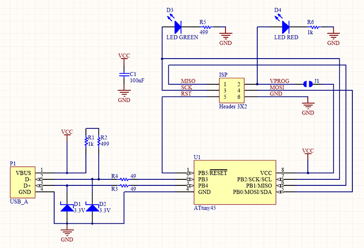
If the wick is old, however, it is not effective. These are the schematics to use when soldering.
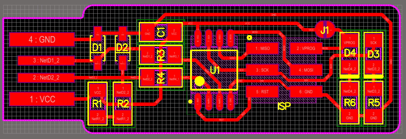
Schematic and PCB
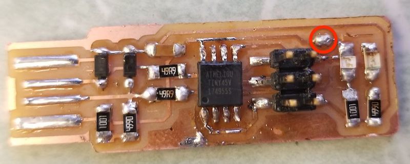
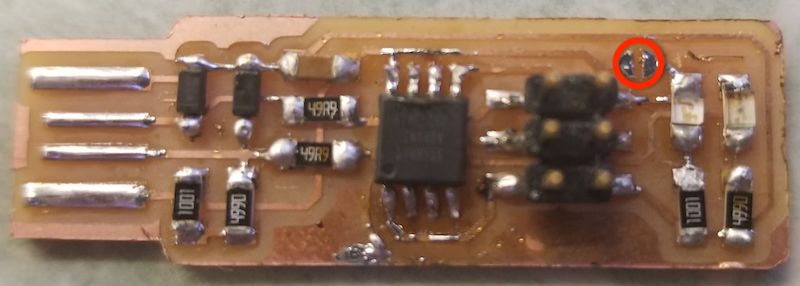
To program the board, I followed the instructions on Brians page. The programmer I used was an ATMEL-ICE. After programming, it is very important to break the bride formed between Vcc and Vprog.
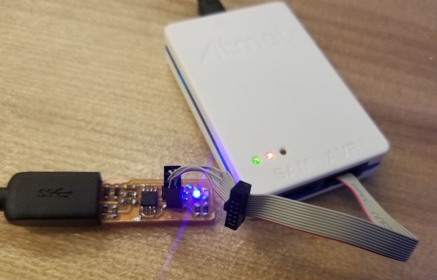
Then I flashed the board with Neil's code and this was the terminal output. I used the lab ubuntu machine.
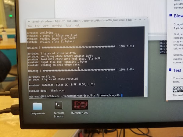
The board is now done!
This was the test for the group assignment for milling that can be achieved with the 1/64 tool bits
