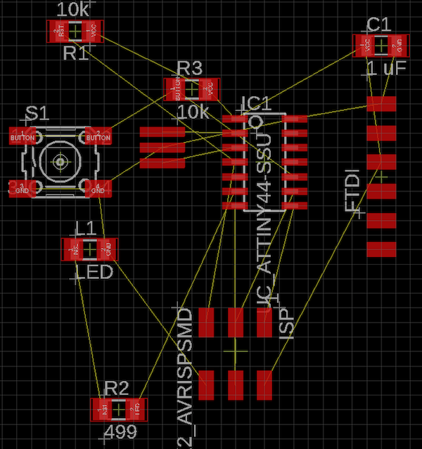
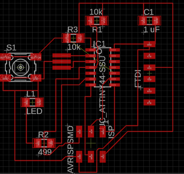
This was the circuit I designed based off of Neil's hell boardimage. I added a button, LED, and resistor that can be programmed later. I used an ATTiny44. The design itself uses a pull up resistor. It keeps the voltage at a known state until the signal is interrupted when the button is pressed. For it I used a 499Ohm resistor. Anything higher should also work.
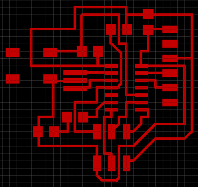
This was the final board traces image ready to be milled. The final image shoudld be monochrome with no grid lines as shown.
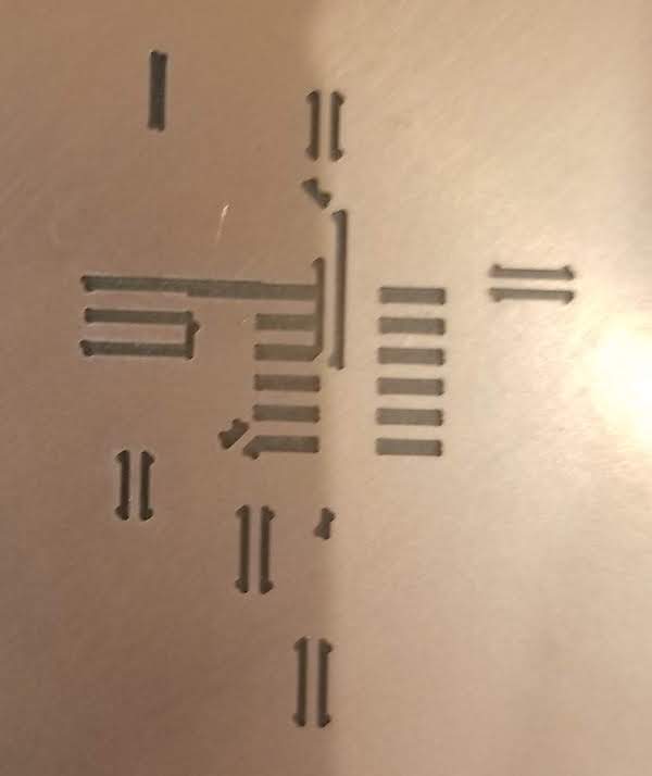
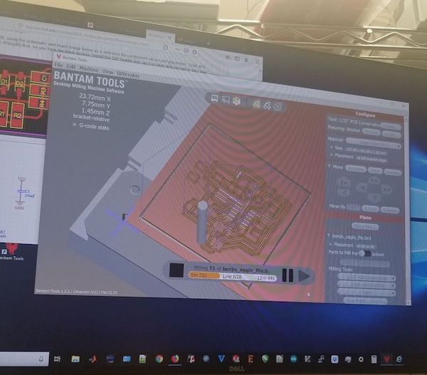
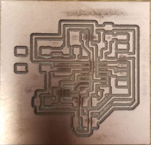
This week I used the othermill. I found out that it is easier to use but needs most post production work. I had to clean off the edges by sanding and went on to remove and weed off unnecessary copper bits. The first time through the board was somewhat scratcy so I had to change the milling piece to a new 1/32". Then these were the results.

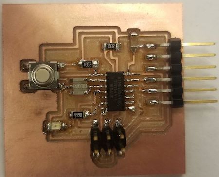
I then went on th solder the board. It is best if you solder one connection from your piece down to the board, even if it is not perfect, then solder the other side to keep it steady, and then come back once again and resolder to make connection shiny and smooth.
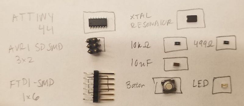
In the components below, I picked up the wrong one for Resonator. I instead got a xtal but needed a resonator. So that one is different in the finished design. Shown to the right.
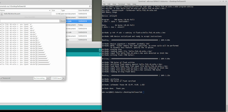
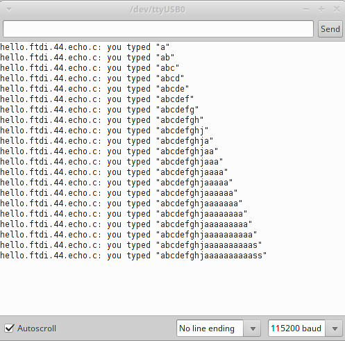
I also used Neil's worksheet for programming the board. The programmer I used was from my week 3 Electronics Production page. I typed the necessary commands into terminal and ran Arduino's serial moniter with the specifications in the screenshot. IT TALKS BACK! It worked. You can see the things I type and the echo's response
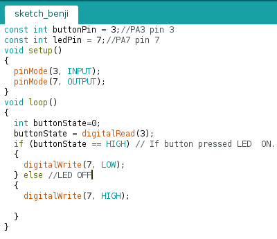
I also wanted to check my LED was working and that the button could control it when programmed. I used a multimeter to make sure it was connected correctly but kept getting Overload. It was telling me I was wrong, and when I tested it with the meters lead's reversed, I would get a reading. But I did place cathode towards ground, so I instead trusted my reading. I then wrote simple arduino code and had to add the ATTiny44 board into Arduino itself through the Board Manager. IT TURNS ON WHEN PRESSED!
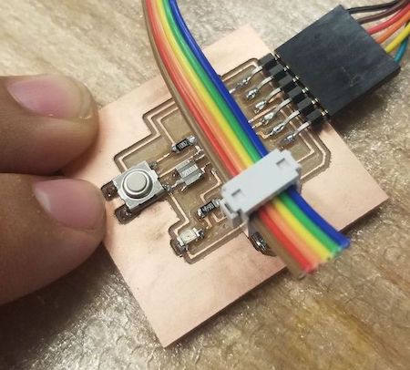
This is the setup to progam using an FTDI cable and my USB Tiny programmer
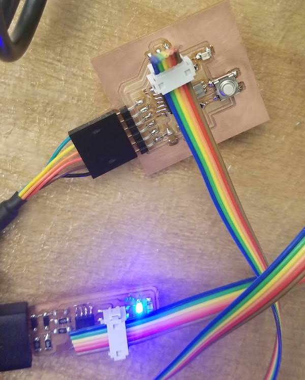
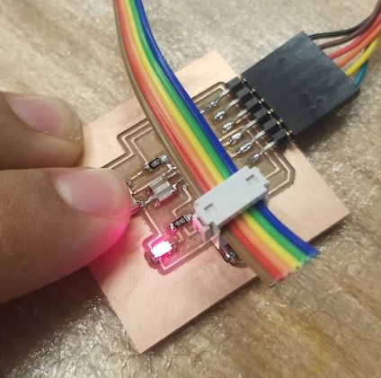
LED responding to button press