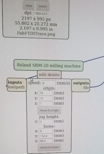
This week is needed to progam. But to do that we need an FTDI cable. There are many in lab, but they get lost or used often so I decided to make my own. I followed the tutorial on the class page and milled and assembled it.
To test the FTDI I used arduino and serial to connect it. I connected pin TX to RX and ran the serial monitter. Whatever I type, the serial should print it back. That was the case so I works well. I used the lab Computer's Ubuntu OS to program it. I will later make another one and try it on my mac.
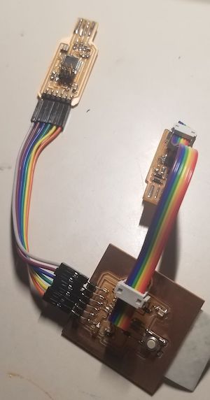
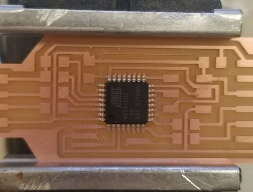
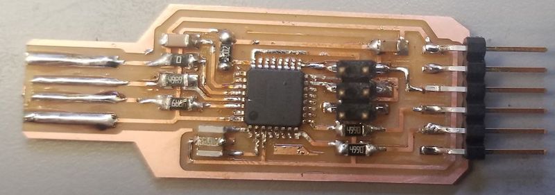
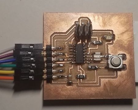
This is the Final FTDI shown below.
To program this week, I used three distinct boards. From left to right, they are the PROGRAMMER from week 3, the HELLO WORLD board from week 5, and this weeks FTDI board. I made each one of these and programmed them all on the lab computers using Ubuntu. They all work perfectly and have not given me any issues.
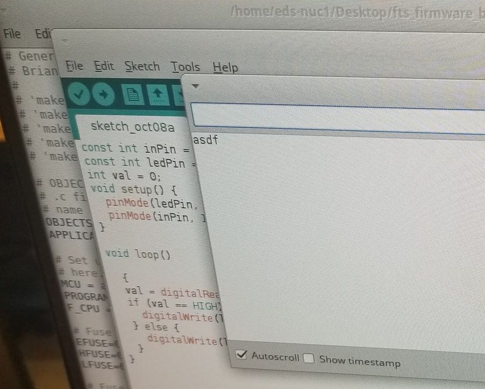
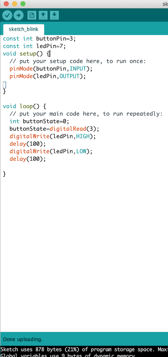
I made three arduino programs that make the light do different things. The first one show below makes the light simply blink.
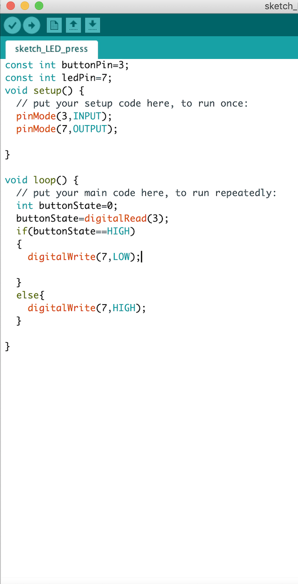
The second program I made makes the LED turn on when the button is pressed. The button pressed is considered as a 'LOW' state and at unpressed it is 'OPEN' in my board.
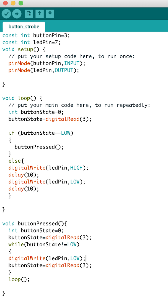
The last arduino program I made is to have the button flicker constantly until the button is pressed. After it is pressed, then it will turn the LED off until the button is pressed again, which sends it back to strobe mode.
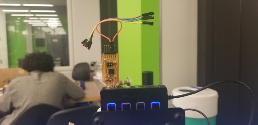
Shown below is the configuration I used when programming in Arduino. I first made the boards and also made the cables that they need to talk to one another. Then I had to install the Attiny board in the board manager in arduino to be able to program. I also needed to use a USB 2.0 Hub to program on my Mac because it did not work initially when I was using a USB C to USB 3.0 and then connecting the boards directly. So I used a C to 3.0 and 3.0 to 2.0 hub.