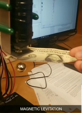
This week I needed to use an input device to measure something in the real world. In my 2.004 class, we did a magnetic levitation lab where we would run current through a solenoid to create a megnetic field that would counteract the weight of the object to levitate. We used two Hall Effect boards, so to recreate that, I wanted to make them instead of buy these.
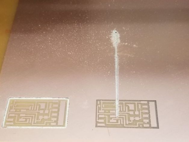
To begin, I decided to use Neil's mag board on the class site. I milled two boards with the 1/64" tool. However when I went to do the outline, I did not check the size and it was apperently 17". The DPI was 78 so that should have raises suspicion but I forgot to look at the settings since it had worked somewhat flawlessly for a while. Well it cut through my board, so I did the traces for a third.
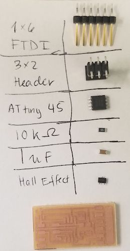
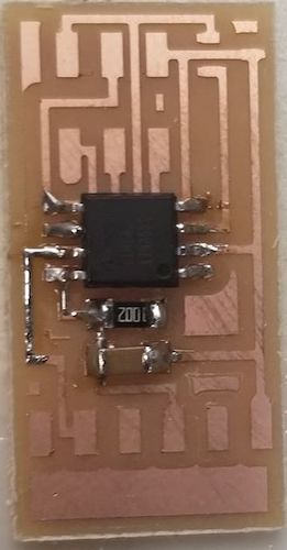
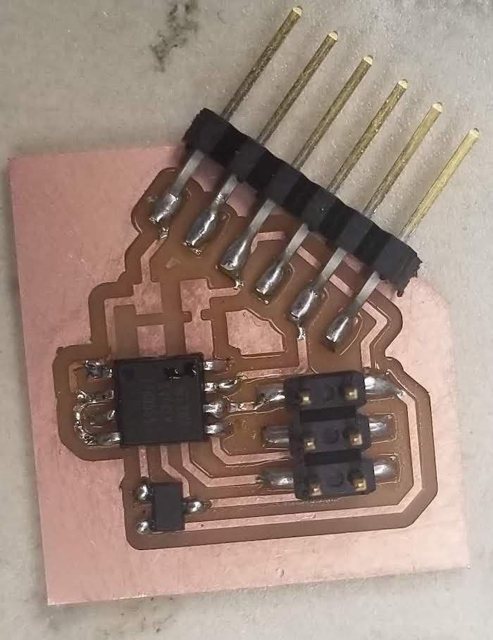
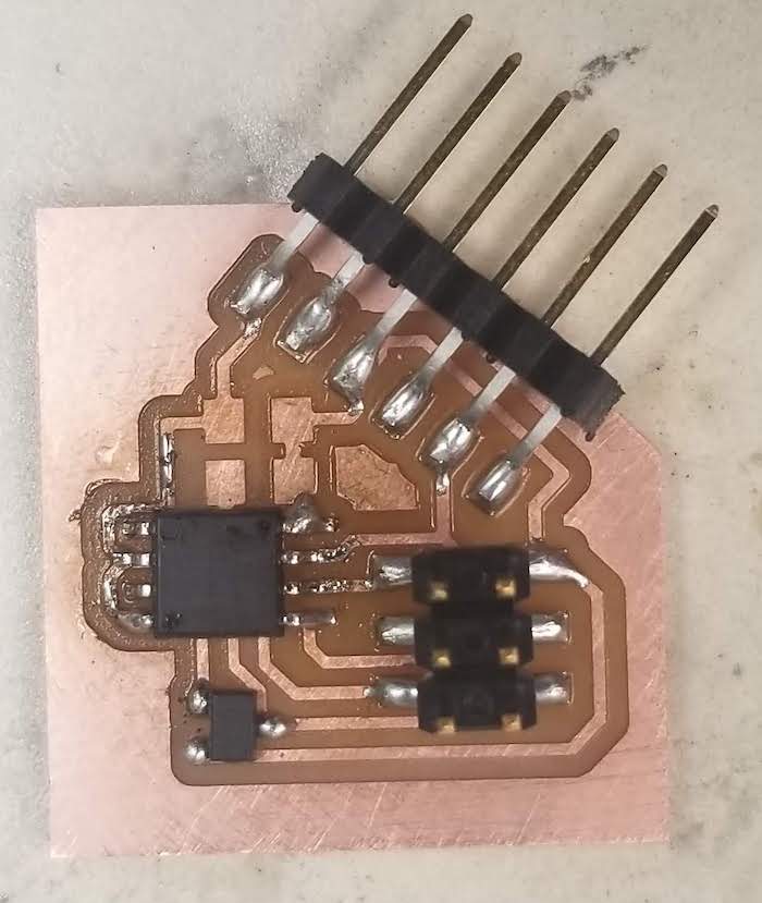
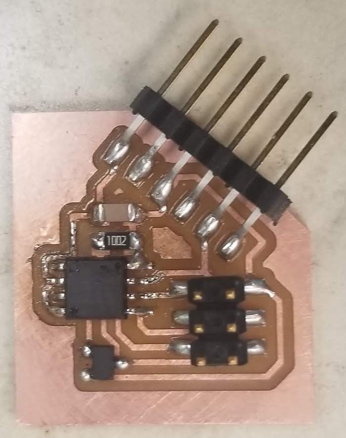
There were onyl 6 components needed as shown below. They are...
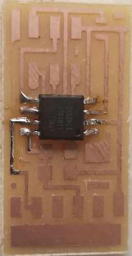
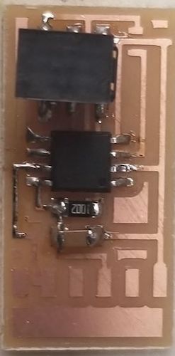
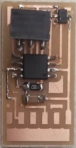
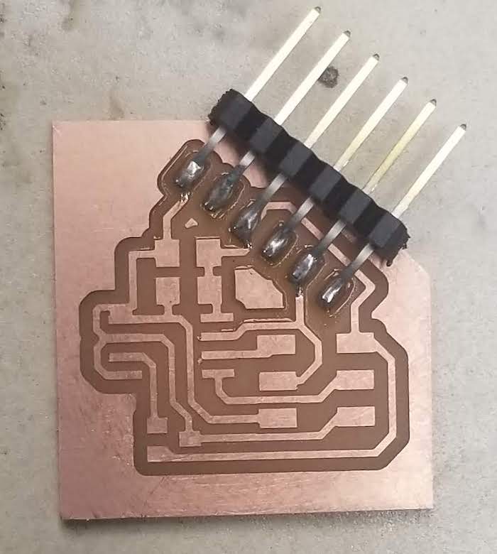
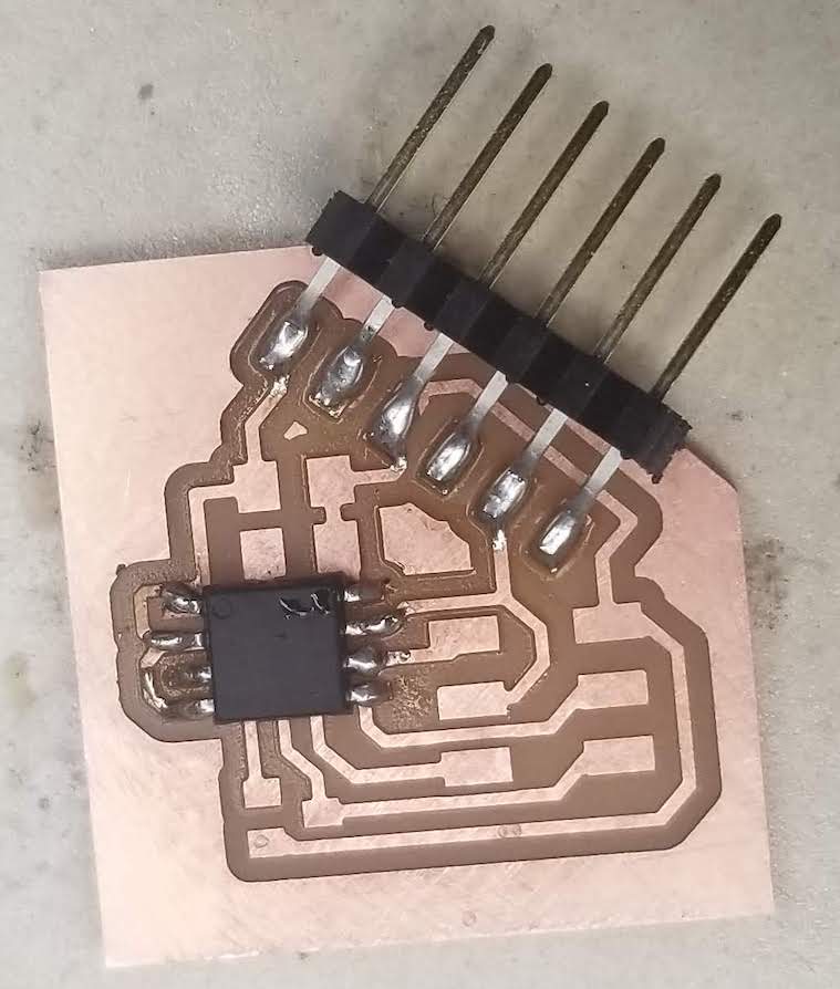
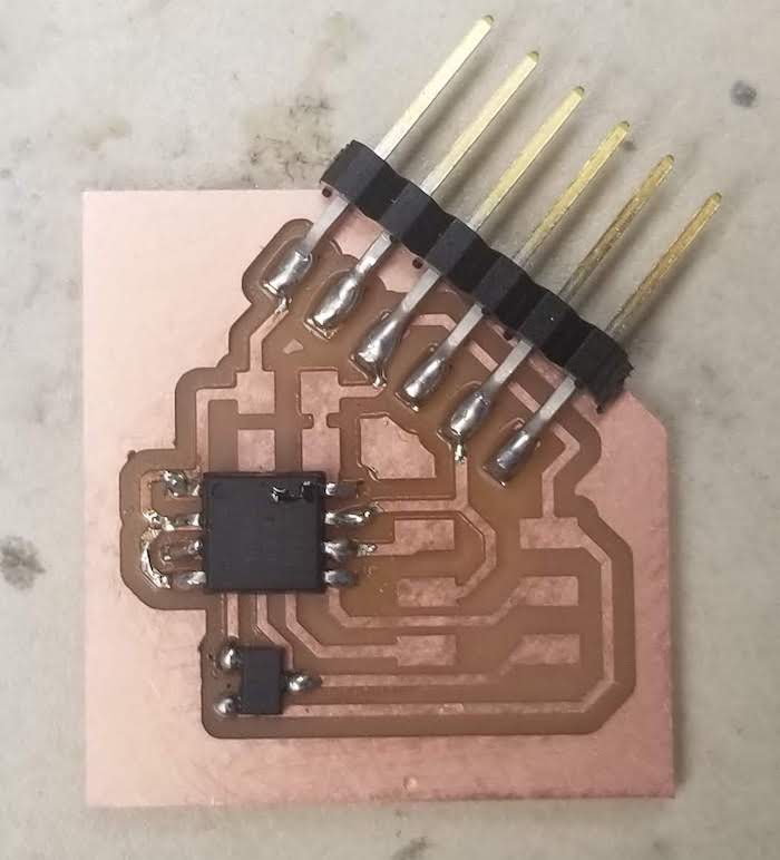
The solder progression is shown. I started form the innermost components and worked my way out. This helps in reaching all places of the board because if you start out and work inward, then you may have soldered components blocking the tool.
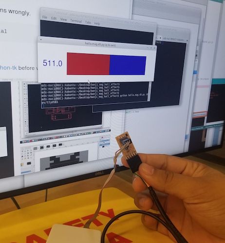
From the CBA class site, I downloaded the "make" ".c" and the ".py" files for the mag board. I saved them into a common folder and using the command line, indexed into it and ran them, first make, then .py. And it works! If the files are not successfully run, then try using this guidefor debugging. Below are several states of the mag board readings.
Board in EECS room with no magnets nearby
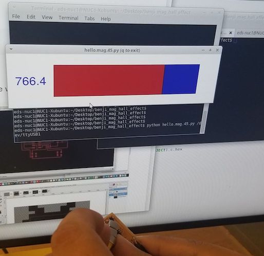
Board in EECS room with positive side of magnet close
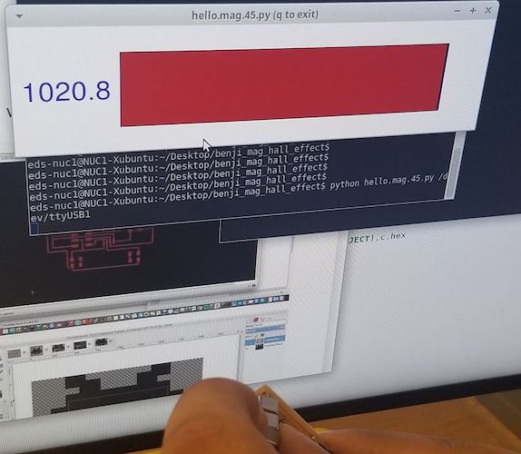
Board in EECS room with positive side of magnet very close
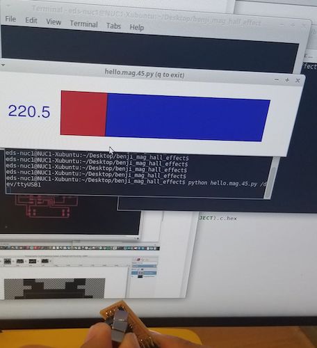
Board in EECS room with negative side of magnet close
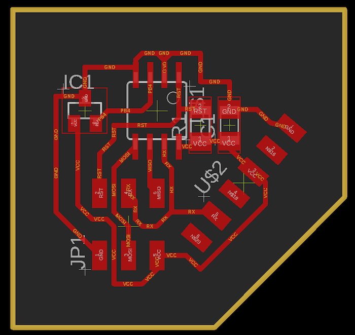
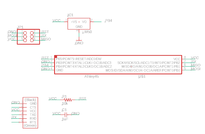
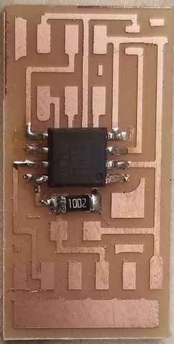
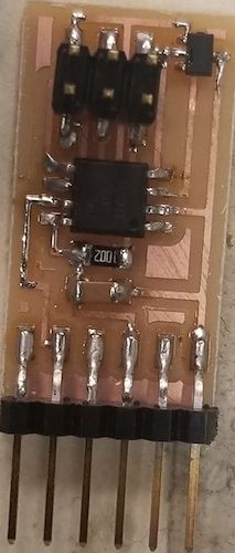
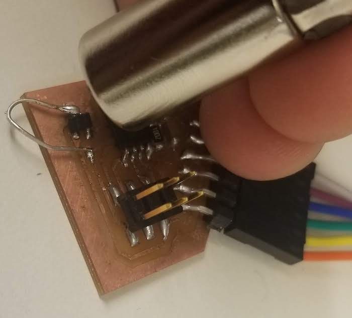
Then I designed my new board in eagle. I created it using the same parts, with settings of 16 wide traces, instead of the default 10, and still using an Attiny45. Here is the process of soldering the board.
When I went to test it, I was getting no readings. I had a the meter display a constant number. Nothing was happeing. I checkked for shorts, resoldered, and compared to my eagle design. Well it turns out, I had designed the magnet to fit backwards, so I would get no readings. I then fixed the current board, re-uploaded code, and it worked.
I did however go back and fix the schematic and the board. They are shown below.