Group Assignment
The group assignment this week was to test the design rules of 3D printing. The EECS section got divided into multiple sections, each of which printed the models that showed the 3D printer's limit in some ways. We just used the STL files from the class website and printed 3D models of "overhang", "clearance", "angle" and so on. These models show the limits of a 3D printer as you try to take 3D printing to extreme angles or precisions. My group specifically printed the "angle" model. The following images shows the result. I had never 3D printed anything before. I learnt the control flow of 3D printing during the group project:
- Load the STL file into the 3D printer software
- Scale the object to desired length scale
- Generate the G code
- Print the model
- Dissolve the support if you printed using a support
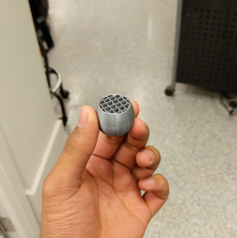
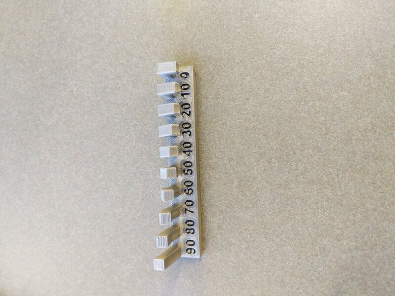 Top View of Angle Model
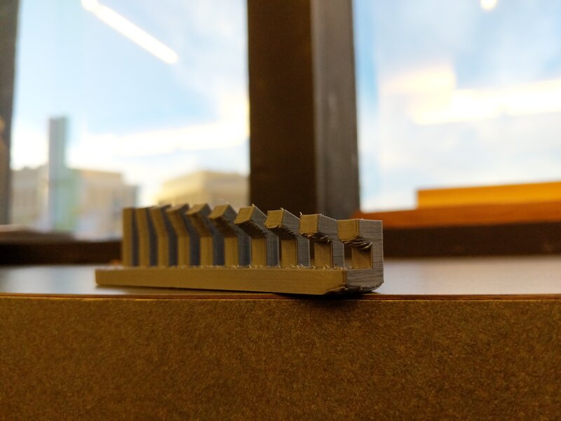 Side View of Angle Model
3D Print Self-Designed Object
What to Design?
I spent multiple hours thinking and stressing about what to design and 3D print for the individual assignment. We had to 3D print something that could not be made subtractively (using a mill for example). The simplest thing I could think of was a ball inside a hollow shpere, but that sounded way too simplistic. I looked around on the internet for ideas of things to print. There were some really cool stuff people had printed, however most of them could be made subtractively and still others looked way too complicated for my taste to make a 3D model. I had just started designing things in CAD and wanted to keep things simple for now. When I could not come up anything I should design, I went to the EDS lab and the TA there, Prashant, gave me some ideas. I decided to design a vase. It sounded easy to design and could not be made subtractively.
Designing the Vase
I had still not settled on the CAD design software to use. Because of its simplicity, I decided to use FreeCAD to design the 3D model of the vase. I made an outline, shaped like a snake, and then revolved it to get a vase-like surface. However, the surface had no thickness. To actually make it printable, I had to convert the surface to a solid and give it some thickness. However, I could not convert it into a solid. After more than an hour of trying to convert the surface into a solid, I gave up on FreeCAD and decided to redo the entire thing in OnShape. My design was simple enough that I did not feel bad starting all over in OnShape. In OnShape, I did a similar thing, I made a poly-line and revolved it to get a vase. It was relatively easy to add thickness to the surface and convert the surface into a solid. I then exported the vase's 3D model into a STL format file.
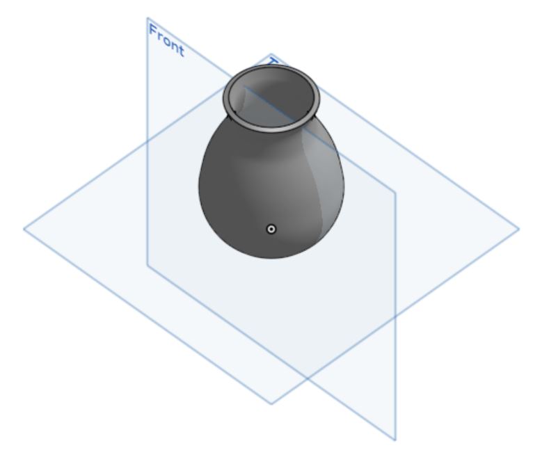 CAD Design of Vase
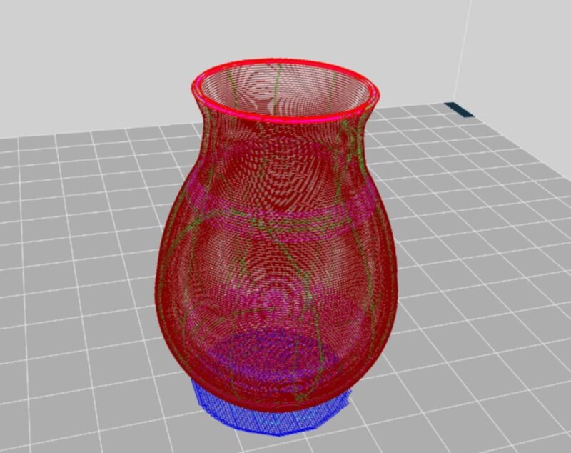 Model by CURA before printing
Failure Printing the Vase
I used the CURA app on my computer to generate G code for the 3D printer. Everything looked fine, so I went ahead and started printing. Halfway into the printing I realized there was an infill to the vase although that infill had not existed in the STL model. I immediately stopped the printing since this wasn't what I had wanted. I and the TA, Isabel, analyzed the "slice" of the model CURA had generated and indeed there was an infill. That did not make sense since the CAD design itself had no infill. Isabel performed some hacks in CURA to get rid of the infill and we started printing again. I left the printer running overnight hoping to come back the next day to retrieve my 3D printed vase.
 Infill in the Vase
Second Failure in Printing
I got an email from Anthony the next afternoon which said my 3D printing had failed. I went to the lab and found that halfway through the 3D printing process, the base of vase had tumbled resulting in a mess like the following. Anthony had tried printing it again for me, but both times the printing had failed. The problem was that the base of the vase was small and as the printer printed the greater heights, the small base gave up and the entire thing wobbled. To prevent this from happening, we decided to print the vase on another printer.
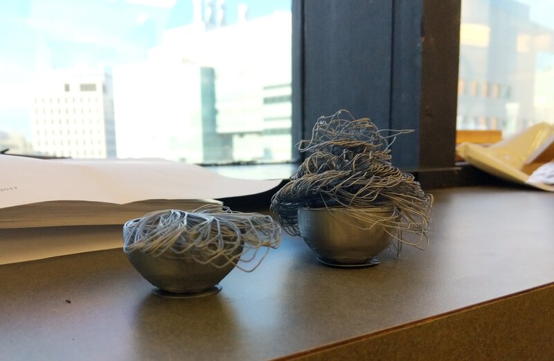 Two Failures
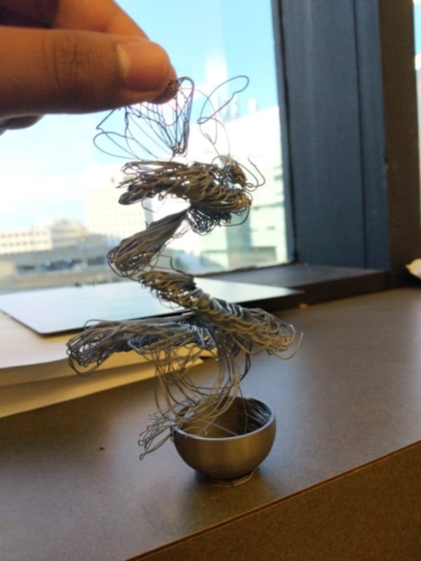 Beautiful Mess
Third Time's The Charm
On the next printer, I had to generate the G Code again. In the slice of the 3D model, once again, we saw the same infill as last time. This was a completely different software, so why did the infill appear. Pretty soon we discovered that the STL file I had exported had the error. When I had exported my CAD model to STL, not only had I exported the solid, but also the surface part. The surface part had generated the infill in the G Code. I fixed the error soon and started the 3D print once again. And this time, the vase printed out almost perfectly.
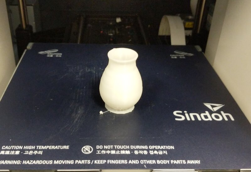 Successful Print
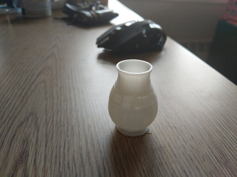 In Dim Light
3D Scanning
There were some powerdrills lying around in the lab and I decided to scan a powerdrill. The EDS lab had a couple Sense scanners. I used them to scan a powerdrill by putting the powerdrill on a table. The first time around, the drill part of the powerdrill did not come out very nice, so I gave it another shot and next time was much better. It still missed to capture the top, and there were some holes there (see the image below) but the solidify tool fixed all of that.
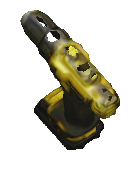 Holes on top of 3D scan
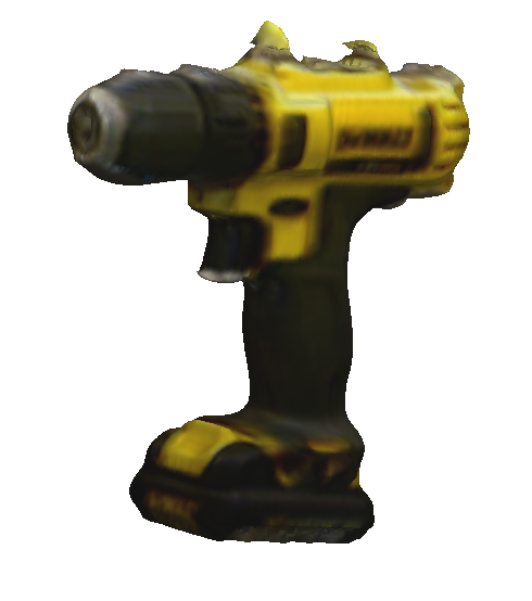 Solidified Drill