Relation to Final Project
I now have a clearer vision of what I want to do for my final project, and I decided to use this week towards the input devices used in my final project. For my final project, I am making a wearable that would detect human falls. Human motion detection involves use of accelerometers and gyroscopes. I am using Adafruit's BNO055 Absolute Orientation Sensor board to measure acceleration. For this week, my purpose was to start retriving acceleration data from Adafruit's BNO055 breakout chip.
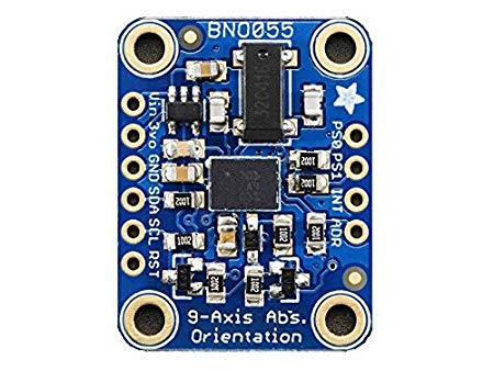 Adafruit BNO055 Absolute Orientation Sensor
Circuit Design
I am using the ESP32 as my microcontroller for the final project, mainly because it has integrated WiFi functionality. In particular, for now, I am using the ESP32 breakout board on a breadboard. That's because I plan to go through multiple iterations of the circuit design as I work towards my final project. Making a PCB board for every iteration with complicated parts like the ESP32 felt very redundant and time consuming especially when I am in the testing phase. If anything goes wrong in the PCB board making process, I would have to redo it from the start. It takes a lot of time and resources, whereas using a breadboard, I could test things very quickly. Later on of course, I will convert my design into a PCB board.
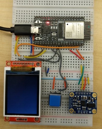 Breadboard with the Accelerometer
The BNO055 uses the I2C protocol for communication which means it only needs to connect to two lines from the master: SDA and SCL. The diagram below specifies the standard SDA and SCL pins on the ESP32. I connected the SDA and SCL pins of the ESP32 with that of BNO055. I also connected the Vin and GND pins to 3.3V power and GND respectively.
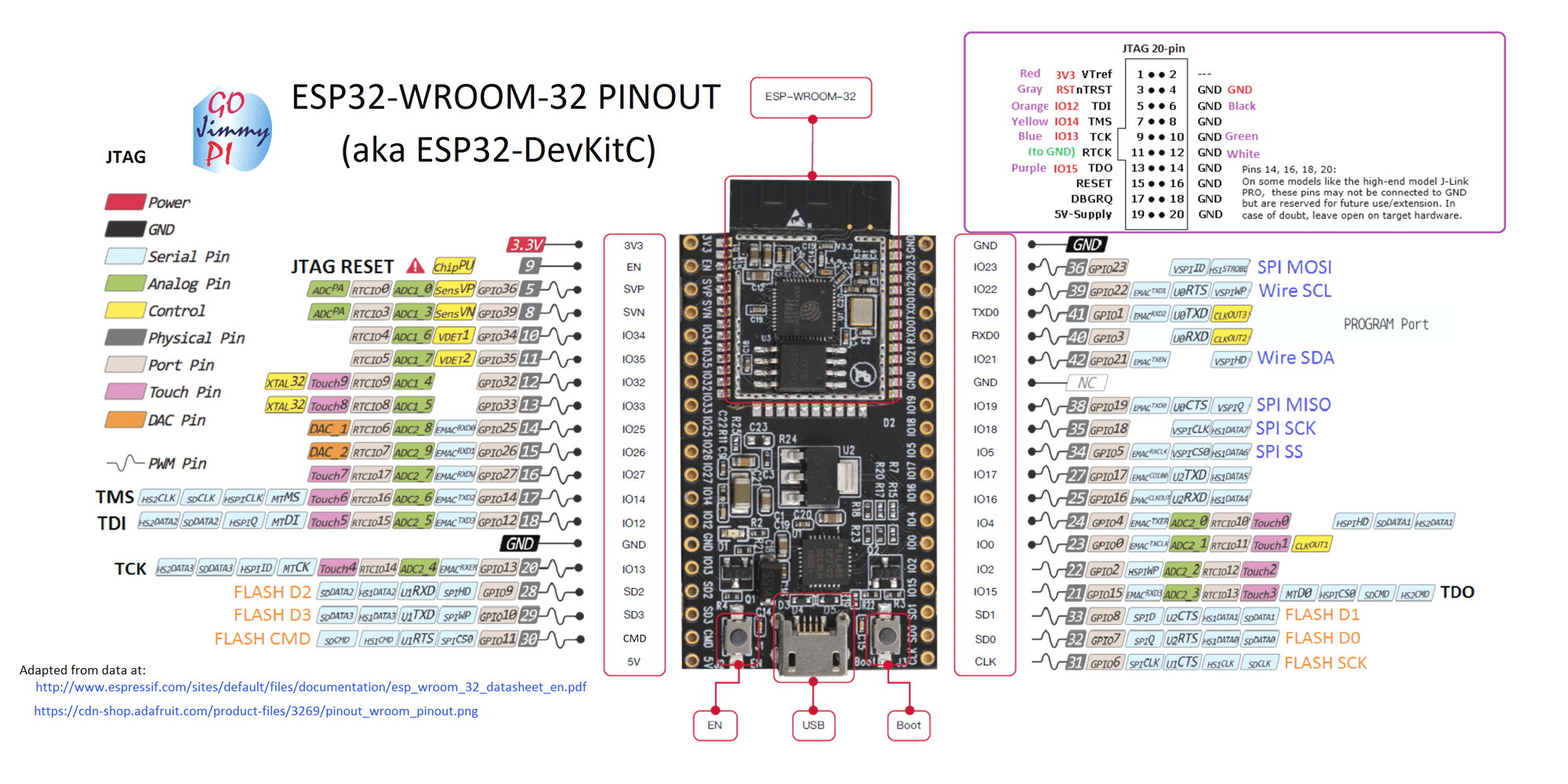 ESP32 Breakout Board Pins (Credit: Components101)
Programming
Programming the ESP32 to read the accelerometer's readings from the board was relatively straightforward. Adafruit's Webpage on the BNO055 Absolute Orientatiton has good documentation on how to use it with Arduino. I followed the steps on their webpage to program the board. My program was slightly different than theirs. On top of recording the acceleration at each loop, my code recorded the acceleration values averaged over the last few timesteps. The code I wrote for this week can be found here. Without too much debugging I was able to get the accleration values onto the screen. And as I moved my board, I could see the values on the serial monitor change. The plot below shows the graphical version of the accelerometer readings along the 3 axes.
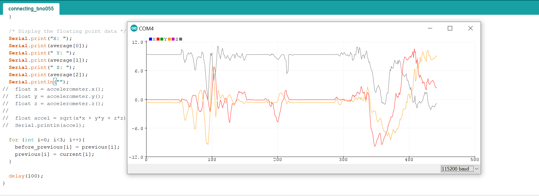 Plot of acceleration values