Week 11: Networking & Communications
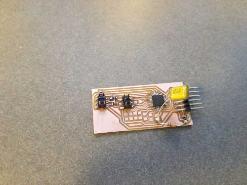
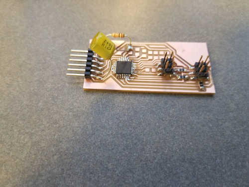
For this week, I reused the board I made a few weeks ago. It already has two ISP headers on it. The first is for programming and the second is an easy way to connect two boards together for an SPI connection. Both boards can actually be identical, and the pins and directions are handled in software.
For an SPI transmission, a clock signal is sent so the receiver knows when to read the data line. A separate ss line is normally high but brought low to signal to the receiver that a message is starting. Since the ATmega328 can be programmed using standard Arduino, I've included some pseudocode.
On the transmitting side, the clock signal is started, and then the ss line is brought low to signal that the message is starting. Then, the desired value is shifted in. If more data than can be held in a single value is to be transmitted, you can just call shiftOut multiple times. Once the data has been transmitted, the ss line is brought high to signal that the message is over. Once the message is over, the clock signal can be ended is another message is not being sent back.
tone(CLOCK_PIN, SPI_FREQ);
digitalWrite(SS_PIN, LOW);
shiftOut(DATA_PIN, CLOCK_PIN, LSBFIRST, value);
digitalWrite(SS_PIN, HIGH);
noTone(CLOCK_PIN);
On the receiving end, the data technically only has to be read out. The complicated part is that this has to happen when the ss line is brought low. I recommend attaching the receiving function to an interrupt so you don't have to worry about transmissions arriving throughout the rest of your code.
if (digitalRead(SS_PIN) == LOW) {
  byte value = shiftIn(DATA_PIN, CLOCK_PIN, LSBFIRST);
}