Week 14: Wildcard Week
Sheet Metal Fabrication
The main goal for this week was to bend a sheet metal model of my room. I've drawn out the floorplans before, but this seems like a reasonable idea.
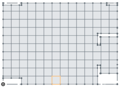
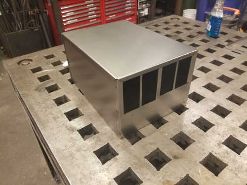
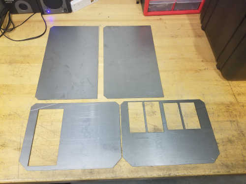
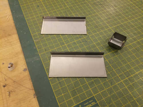
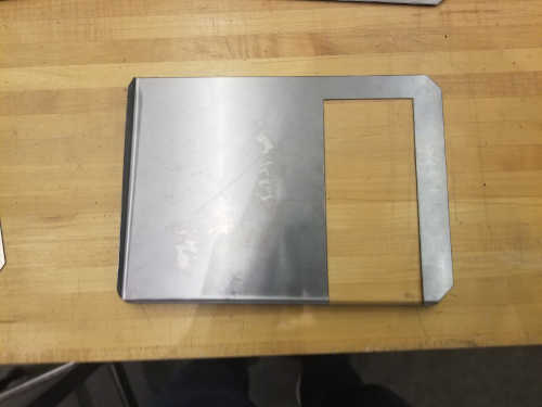
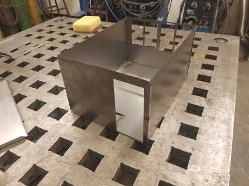
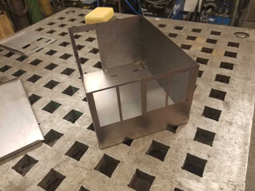
First, I designed the .dxf files in OnShape. I think there's a feature to generate sheet metal plans from given 3D parts, but I just designed this by hand. Although the floorplan does have a couple annoying parts, the overall shape is still pretty simple. My room is actually 10'x14', so I designed as 1:12 scale model. Since I was limited to 24"x24" sheets, I modeled each wall separately. Every corner has some internal walls, so I have space to hide the joints. I'll come back to separately bend custom parts to fill the internal walls. Those are simple enough shapes that I'll just cut them on the shear and the corner sheer.
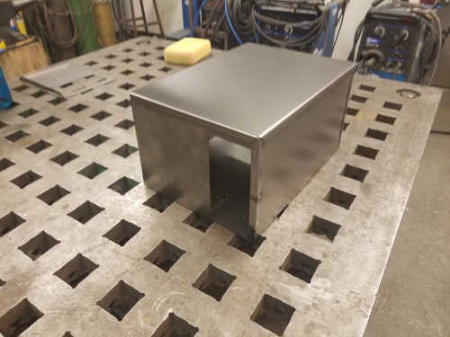
Since we had the spot welder demonstrated during the tutorial, I decided to use that to join the box together. Spot welding is already pretty unsightly, and I did a terrible job with it. Given another shot in the future, I'd probably drill and rivet it instead.
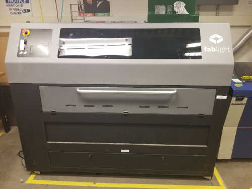
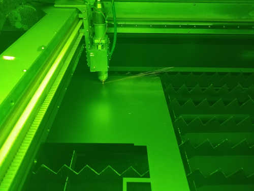
All my parts were cut out of 2'x2' 22 gauge sheet steel on the FabLight in the CBA lab. You just need .dxf files which are turned into .fab files on the computer next to the FabLight. The section on the front of the FabLight folds out and down, and the tray pulls out. There are some small clamps on the left side. Note that the machine's origin is near, but a little inside the front left corner of the tray.
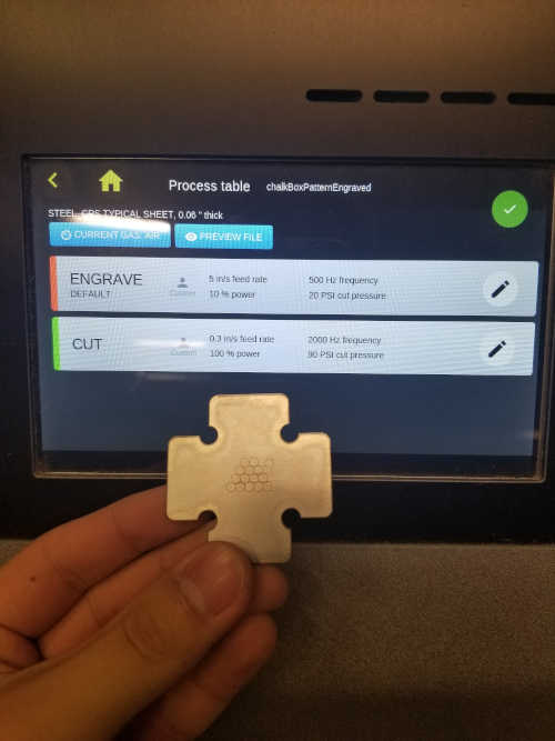
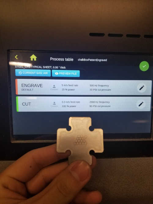

I also fiddled with the engraving settings on the fablight. Going up from 10% to 15% helped a little with the design. The engraving throws up a lot more sparks than cutting does, probably because the sparks aren't going through.

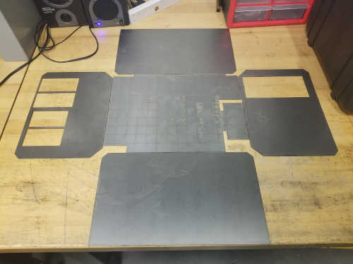
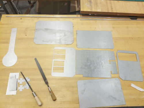
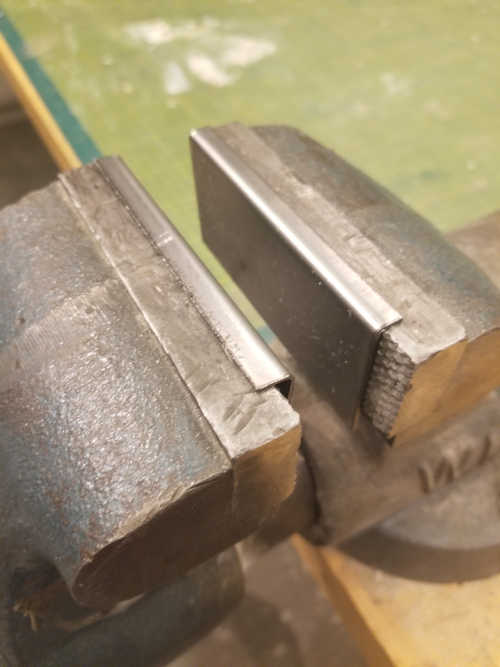
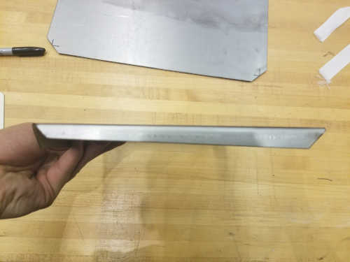
I did most of my bending using the small hand bender and a vise. I bent some scrap metal to make some soft jaws for the vise to avoid leaving too many marks.
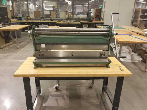
I finished on the finger bender to tighten up some of my bends. I also had to recut one piece because I bent it the wrong direction and bent one side terribly.

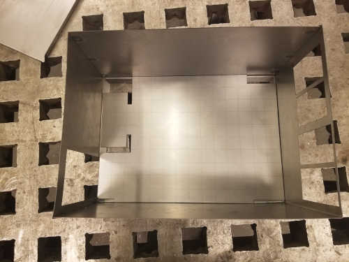
Once everything was bent, I spot welded the walls together. I did the first welds without cleaning the pieces which was a mistake. I alsp was not careful enough with my positioning. The two pieces much be in contact at the point they are to be welded and the terminals from the welder should not touch the metal pieces anywhere else. You should also be careful of holding the weld for too long which can melt holes in thin stock.
Injection Molding
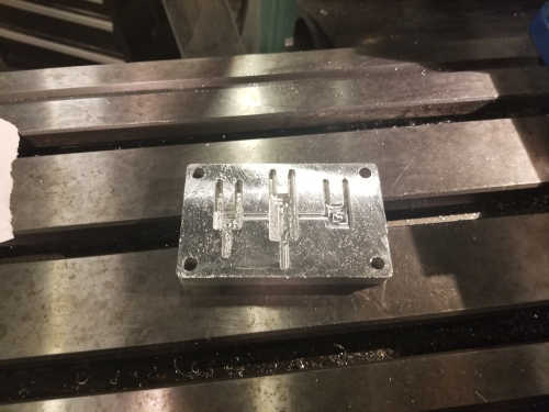
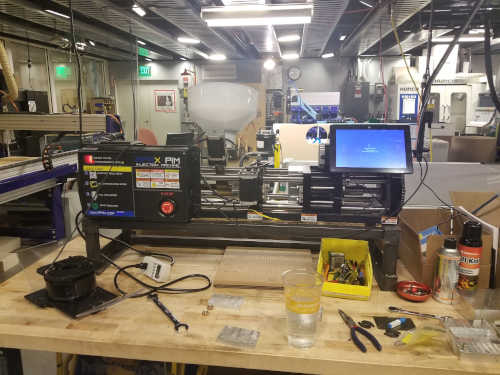
I intended to do some injection molding during wildcard week as well, but we ran into some issues. The process involves milling a two part mold on the Proto Trak and then injection molding on the APSX-PIM in the CBA shop.
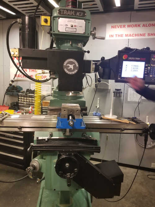
I was going to mold some finger segments for my final project. The segments would fit together and get drilled and pinned for pivots. This part actually makes a bit of sense for molding because I'd need many copies of each part. It's still a pretty small quantity for an injection molded part though. It all starts with importing my files to Fusion to generate machining paths. To go from OnShape to Fusion, I had good results with .step files. We tried initially with a .stl, but it came out scaled wrong. We tried the parameters that had been working before, but I think we were too conservative. The Proto Trak only goes up to 2000 rpm spindle speed, but we set up the paths with 3000 rpm to get a higher surface speed. I think we were still only at 8 in/min which feels very slow for aluminum. We milled it with a 4 flute 1/8" flat endmill which was another mistake. Chip evacuation was pretty poor, and switching to a two flute endmill would have helped a bit. We ended up breaking an endmill. Even though it didn't get stuck and ruin the piece, we stopped because the machining time was a bit ridiculous for such a small part in aluminum. Note that the Proto Trak needs the flash drive to be kept in the machine for the entire program. If you pull it out early, the program stops and you have to start it over from the beginning.
The workflow is you clamp a block in the mill on some parallels and use an edge finder to set your x and y zeroes. You can use the piece of paper trick to set your z zero. Then, you face both sides and start your program. Don't forget to get your zeroes again after flipping the block. We machined inserts for the molds, so we only had 0.5"x2.5"x4" on each half. These inserts were mounted in larger blocks so wall thickness was not overly important as long as we didn't break through.