Week 5: Electronics Design
Eagle
For this week, I replicated the blink circuit in Eagle. There was a bit of a learning curve with that software. Laying out traces is particularly tricky, and I ended up copying sections from boards I had seen before. Note that to be able to route through resistors/capacitors, you need to use the 1206 components in the fablab library. You also need to use the custom 2x3 pin header to be able to route through the ISP header.

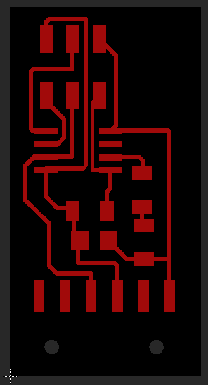
traces.png
outline.png
board.brd
schematic.sch
Fabrication
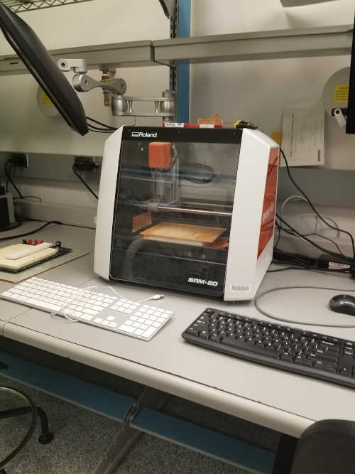
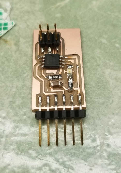
This board was pretty straightforward to make once it was designed. I milled it on the Roland SRM-20 on the EDS lab.
Coding
I decided to just have the board blink a LED. I was able to reference most of the code from an existing board. The main loop just logs a character to serial, toggles the LED state, and waits 1 second before repeating.
while (1) {
  put_char(&serial_port, serial_pin_out, 'T');
  toggle(LED_direction, LED_pin);       //toggle LED pin output.
  _delay_ms(1000);
}
main.c