Week 03
Electronics Production
Theoretically I can do this...
I am use to running around with boards that cost the same as tuition for a semester at MIT. It is pretty exciting for me to get my hands on and design boards. (I know I haven't designed anything yet.) At the same time, I had my 6.002 board that had to be soldered, so this was wicked nice timing. The procedure was laid out for me and away I went.

Premila had used the *OTHER* miller and I decided to try the *THIS* mill machine. I went through the process, saved the file as a .svg and got onto the computer. Unfortunately, the scaling did not work with the scaling. So I switched over to the same machine that Premila used.
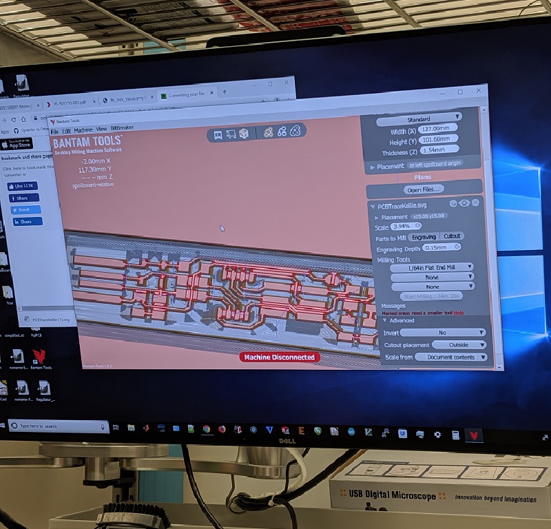
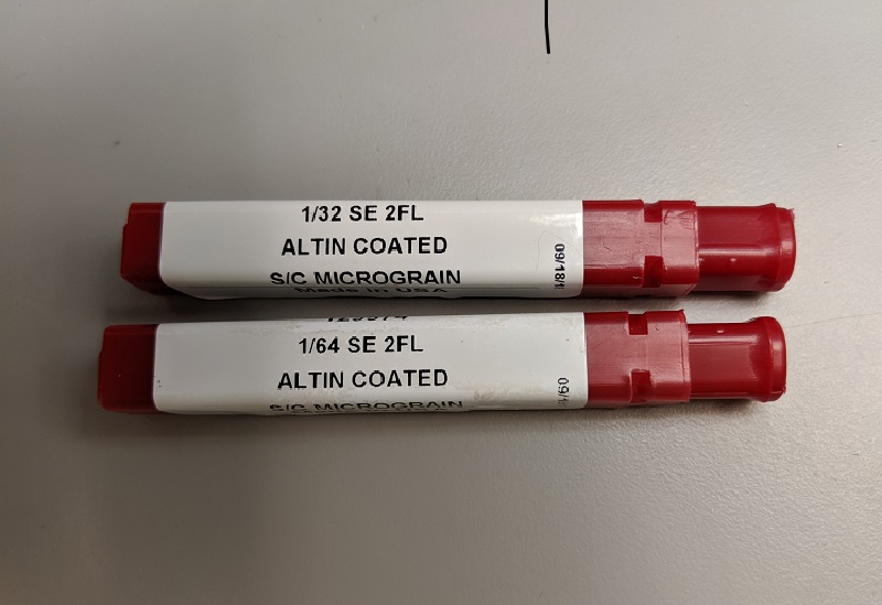
Moving on to the actual milling, I was able to get everything up and running on the *SECOND MACHINE*. I first had to ensure that the proper mill bit was loaded into the machine. Once this was complete, I had to ensure that the bit was properly leveled. If these are incorrect, the milling could be too deep or not even reach the board. I also made sure that I started with the 1/32 bit and moved to the 1/64 bit for the smaller area. This took in consideration for time required for the job, and also wear on the bits.
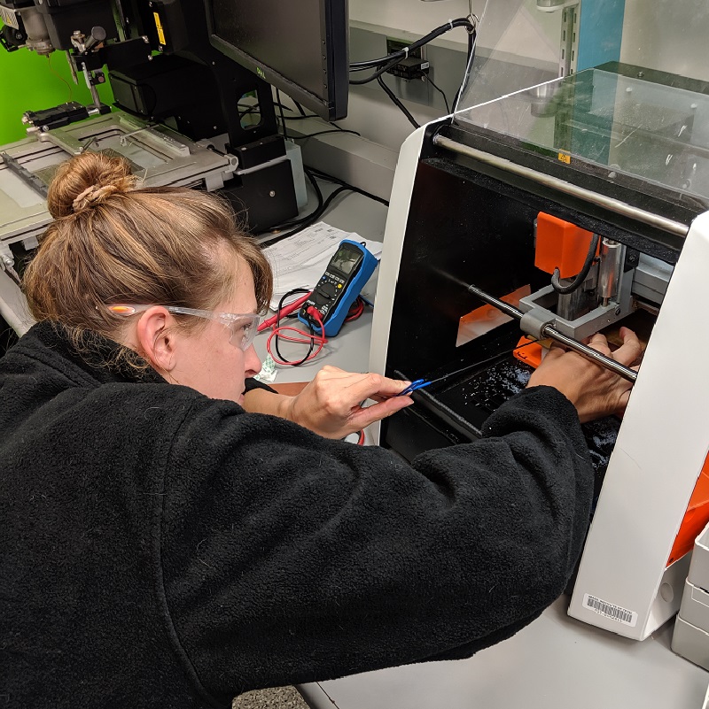
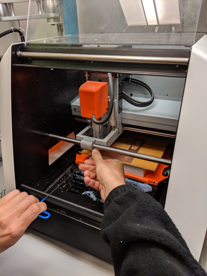
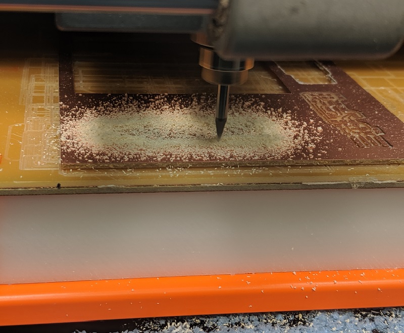
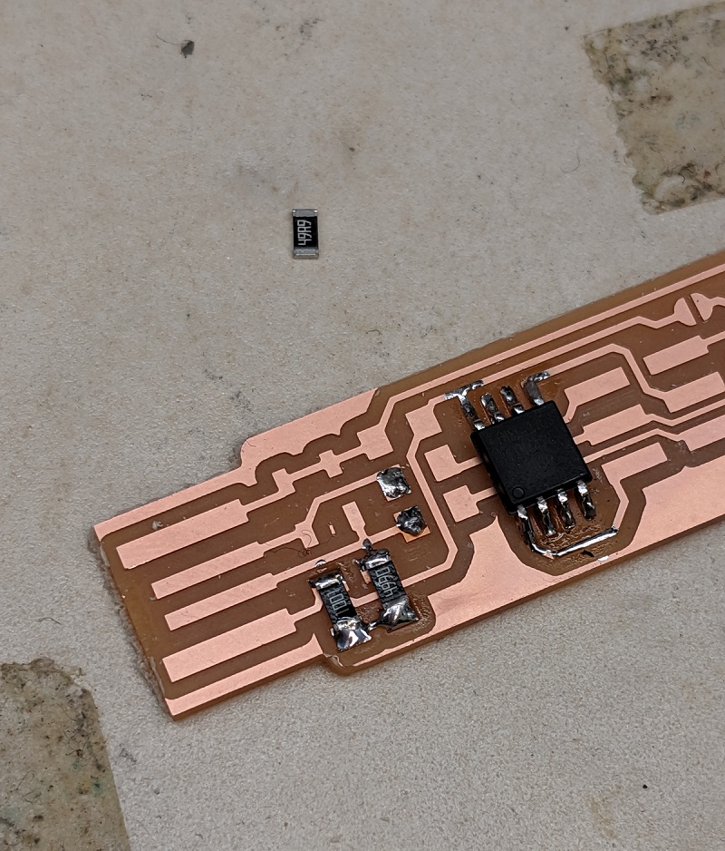
The next step was to mill away! Whoohoooo! It was neat to watch the machine work along the programee. It was very clear that the material was atleast being taken off. We would have to wait and see if it was properly milled. Fortunately, the first pass of tracing and outlining worked really well for me. I did not have any issues with stray pieces, curling copper, nor too much copper being taken off. I got way too excited for soldering, so I forgot to take a picture without any parts soldered on.


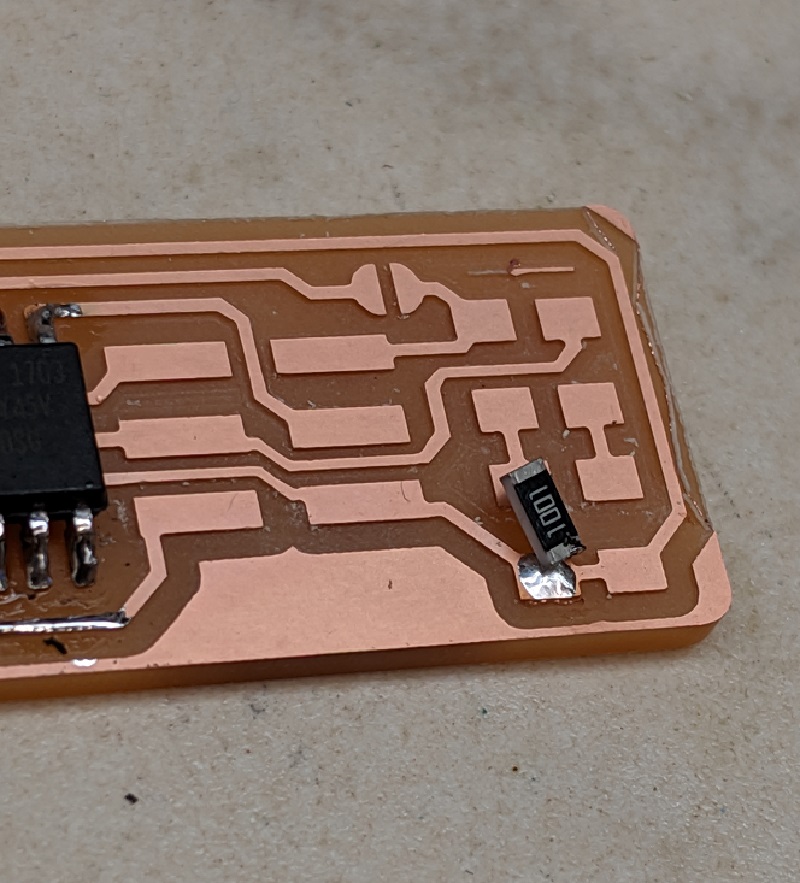
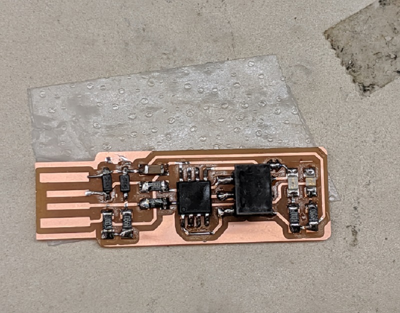
Along the path to component placement, "tacking" down a part allowed for a secure solder. I had to be sure to go back to the tacked side and ensure it was properly seated. At times, I had difficulties getting both sides warm enough at once to get the component seat flush on the board. I focused on making sure that my solders were clean and sturdy without blobbing the solder on.

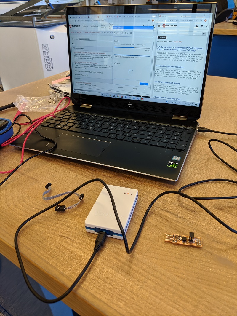
So now the next thing was to ensure that the programmee could be programmed to become a programmer. Would it work? Would all the efforts and trials be fortuitous? Well unfortunately you will have to wait a little while longer, because the errors had just started to be realized!
I worked and tried to program mine with another handmade programmer, however it was just not meant to be. I triumphantly admitted defeat and downloaded Atmel Studios.

So what should I do now? Well we should try another way.

On the plus side the LEDs lit up. Alas, it was time to find another method. To the EDS computer to try again. Finally it was programmed and I was able to move on to the next adventure.