Week 09


Input Devices

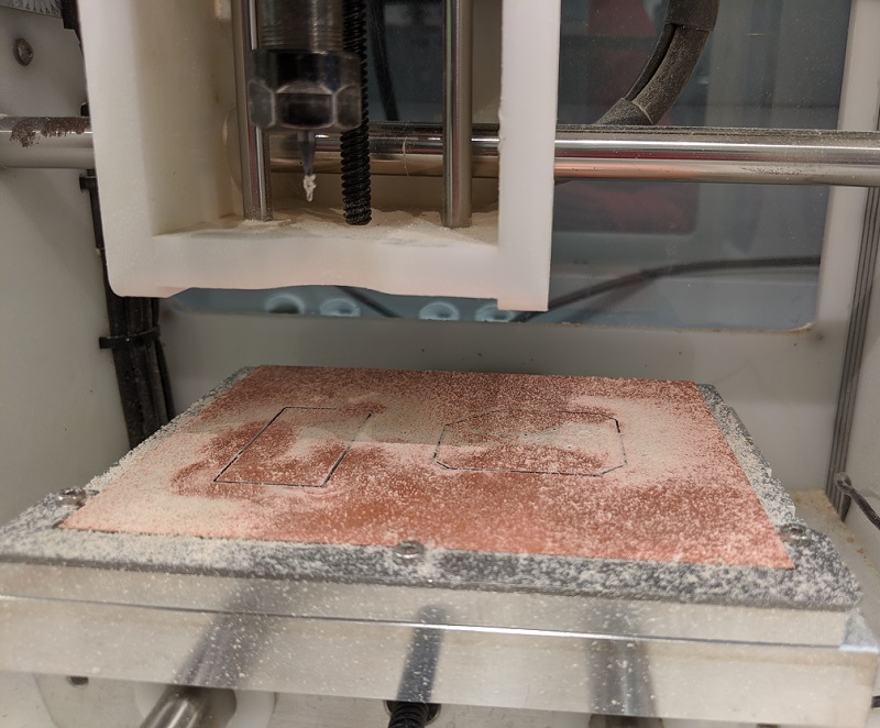
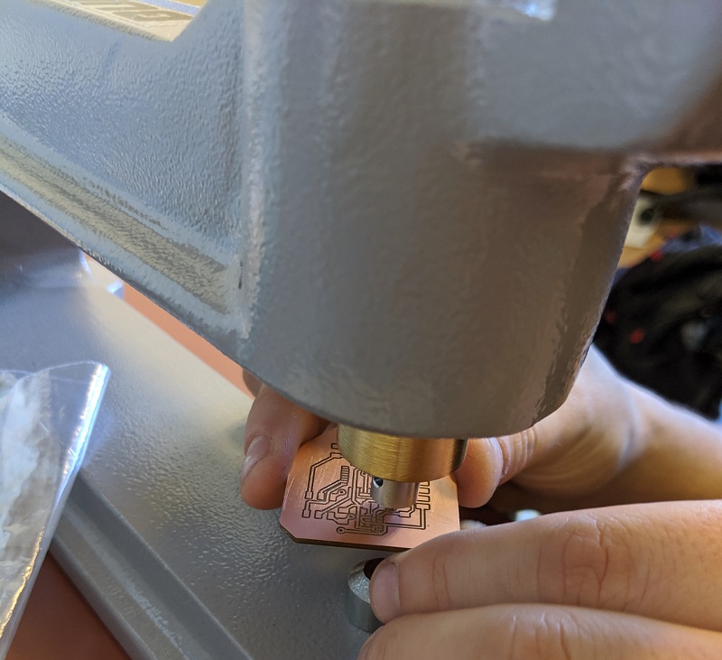
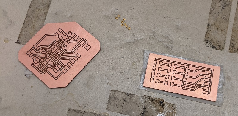
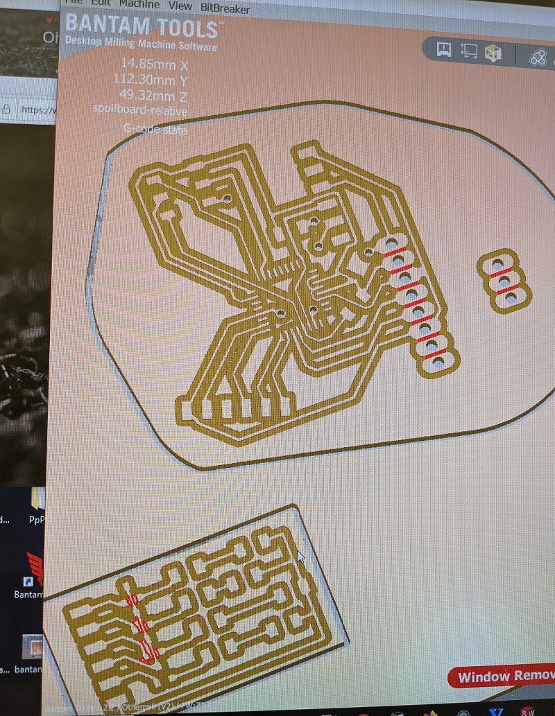
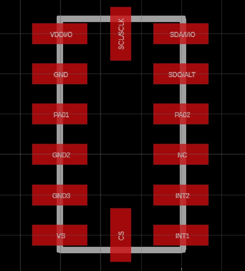
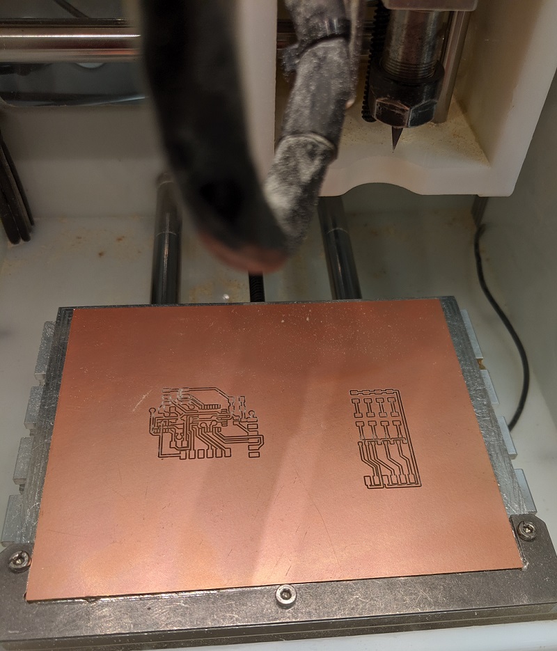
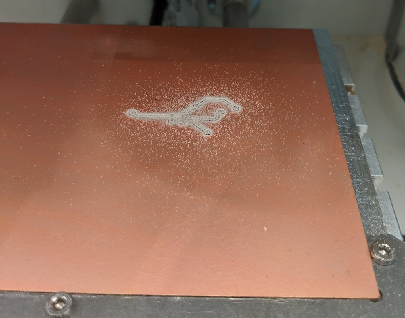
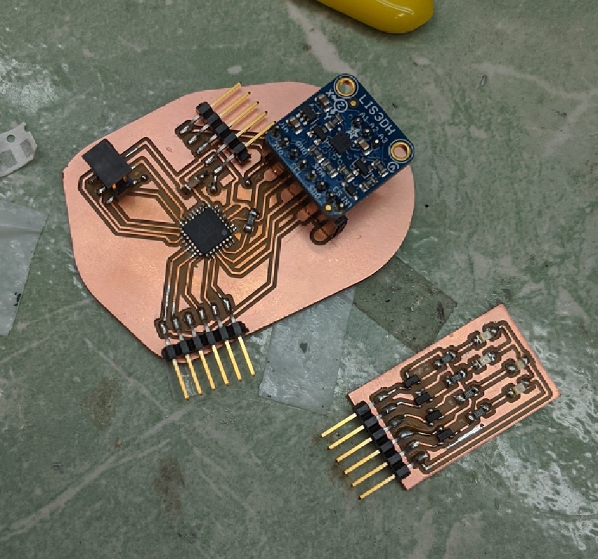
Many of my weeks are starting to run into one another. My board for this week was started a few weeks ago, but it is an updated version of it that moves me a step closer to my final project.


Through a couple iterations I was able to create a footprint for the accelerometer. This footprint works for the ADXL343BCCZ well. At this point I am still waiting to see if the ADXL343 talks with my board or not.


Considering that I was going to need a doulble-sided board for this project, I had to start paying attention to lining up and finding the frame. By using the blunt end of a broken mill bit the OtherMill was able to trace the bracket and get a good idea of positioning.


I also have a second board which will act like a test board for the lights.


As will milling it is a process of switching bits, and flipping copper sheets.


Tracking the mill in real time.


Here the mill is working on the rearface traces, vias, and finally the outlines.


Once the tools were fully milled I was able to find the rivets required to ensure a continuous electrical path. With the machine, they all pressed without an issue.


Finally a comparison between the bare milled boards and the fully soldered boards.


A pre-milled trace and a post-milled completed board. I had significant difficulty with attaching the ADXL343BCCZ accelerometer. After finally getting it on without any shorts and proper connections, a few hows had past. I am unsure what my hourly worth is, but it is definitely more than the $7 I spent on the switch to the LIS3DH Adafruit break out accelerometer board. I was happy that I eventually got the ADXL343BCCZ to work, but time wise the LIS3DH was a much better long term solution for me.


After some light coding data was retrieved! Both in a numerical way, but also in a graph that showed the x, y, and z-axis. This was a huge step in working towards my final project!


Belle got to go to the hardware store with me and gather PVC pipe!