Week 4: Electronics Design
On week 2, we learned how to mill our own PCBs and solder the materials to make the circuits all work. But all that as using a design that had just been given to us without much context. This week, we are designing our own circuits, from the electrical behavior to routing the traces in order to fabricrate a physical circuit.First, we were given a base circuit with a programmable microprocessor.

For the assignment this week, we were tasked with re-designing the above circuit, and adding an LED and button to be interacted with.
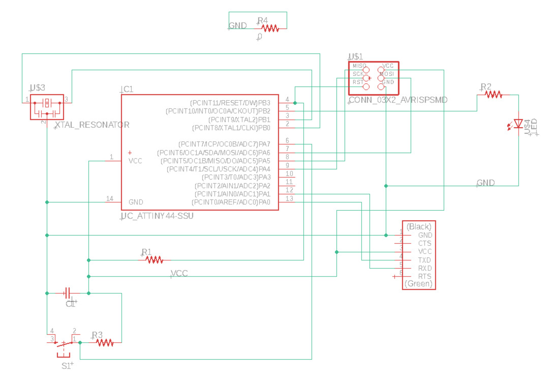
I used Autodesk's Eagle to do the circuit design. First, I started by examining the connections in the reference board, and then drawing a schematic in Eagle to match. It took a bit of setup before anything would work, which involved importing the fablab libraries, but eventually I was able to connect everything together in a (somewhat) clean manner!
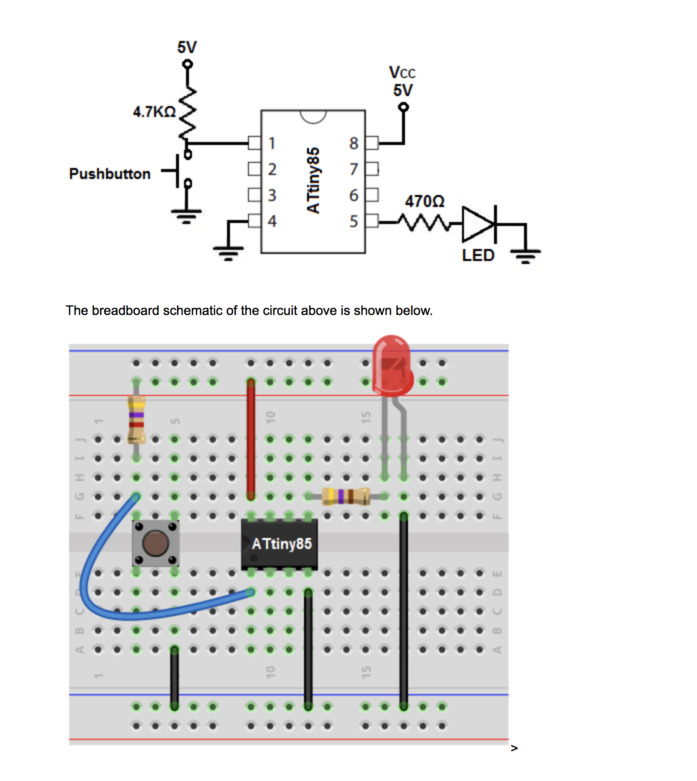
To figure out how to attach the LED and button, I used this reference, which shows how to implement the pull-down resistor for the button. This resistor is important because when the connection to the button is severed, we want to send the ground voltage rather than some noise from the air. The resistor infront of the LED is just to make the light not shrine so bright.
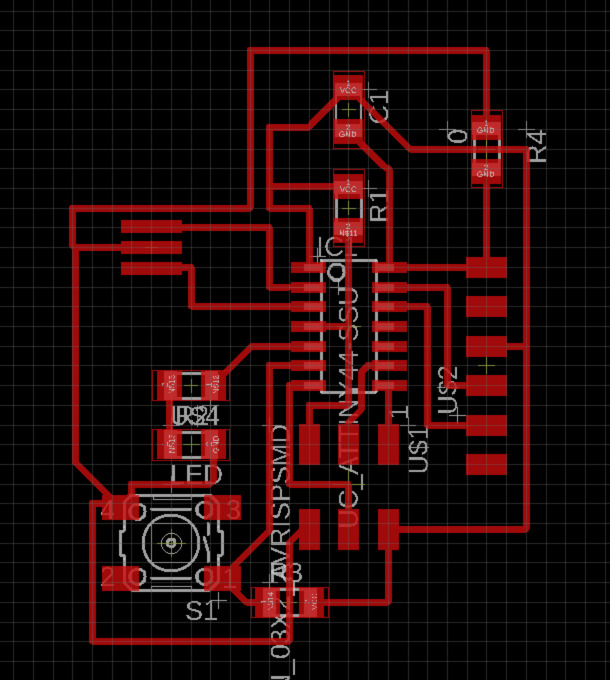
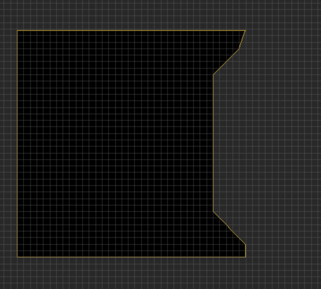
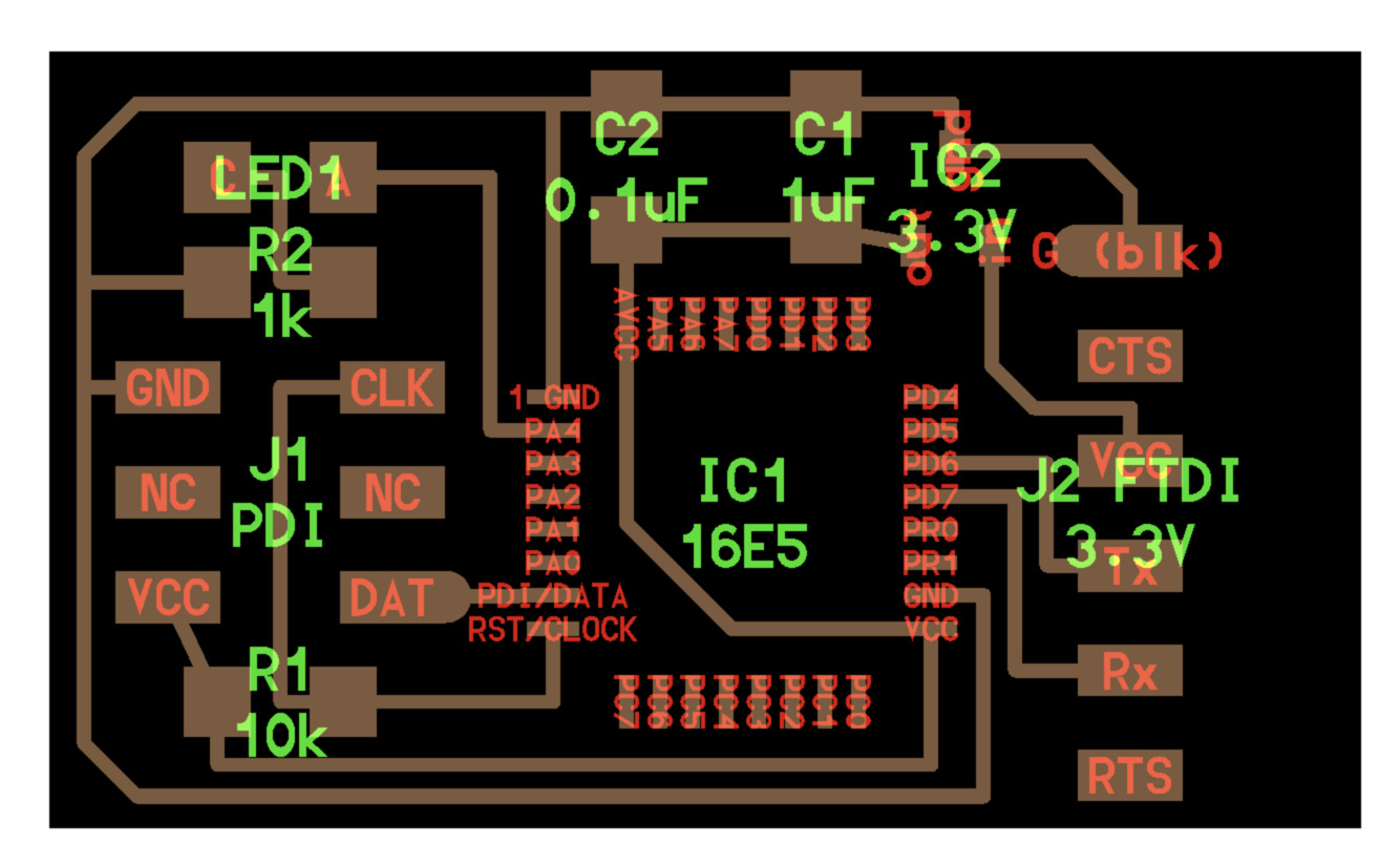
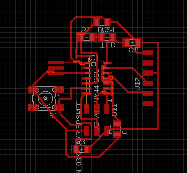
As it turned out, that first iteration of the traces had too many tight squeezes, and I had set the trace thickness to 8 instead of 16. So Eagle started complaining when the design constraints were imported, and I had to start over. In the second iteration, I was able to route all the traces around each other, and I only requried a single 0-ohm resistor to jump over a trace. I also drew a quick polygon for the boundary of the board for the mill to cut out.

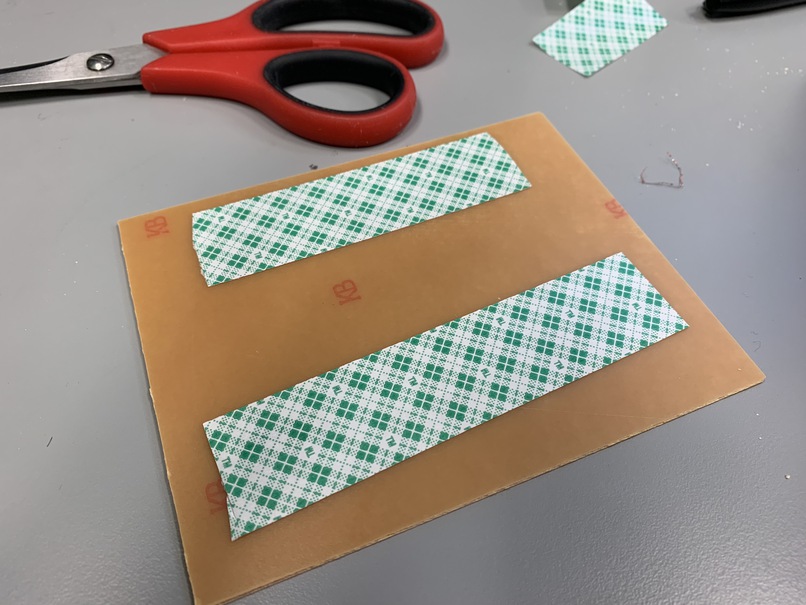
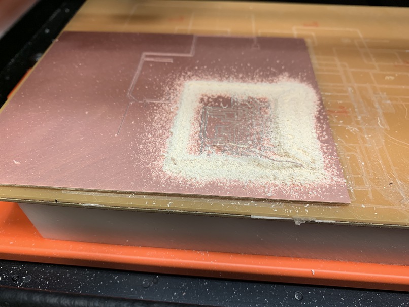
Finally we could mill the design! The setup here was exactly the same as in week 2: turn on the mill, start the modserver, and load the PNG of the traces into mods. It was important to export the DPI as 150 and set the DPI in mods to 300, for some reason. Also, it is important to actually turn on the electricity!! Which I forgot to do and was confused on for a good 30 minutes. Also, I made sure to put the double-sided tape where the actual board would be cut.

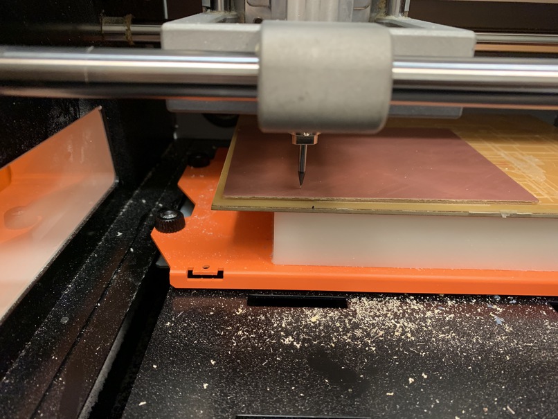
The big cut in the back is when I set the DPI wrong, so the mill started cutting out a jumbo-sized circuit.

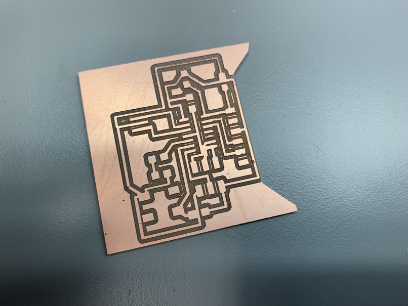
But eventually, I got the settings correct, and all the traces were milled out! There were a few portions where the mill did not cut exactly straight, so I had to manually go through with a knife afterwards and fix up a few things.
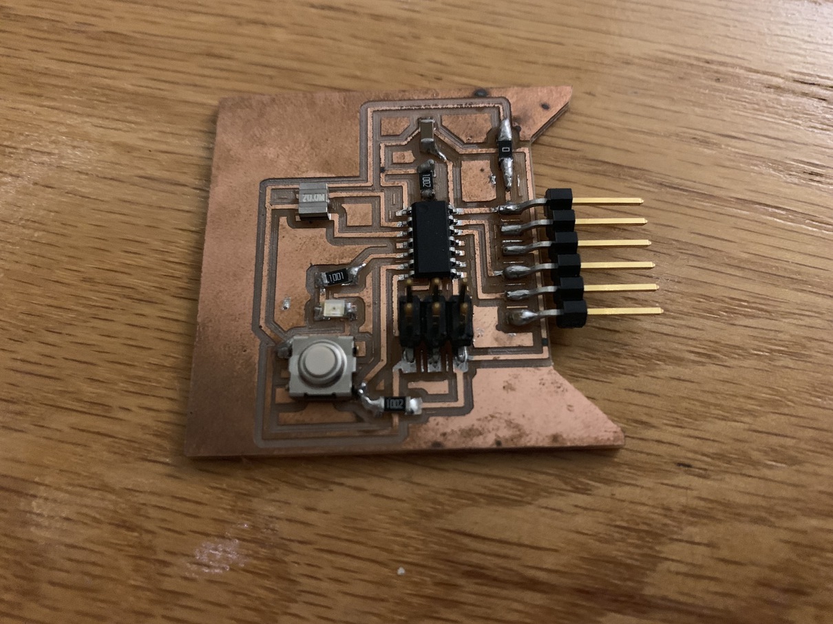
At last, I soldered on all the parts and checked the connections with a multimeter. I used solder paste for a lot of the finer parts like the microcontroller and pinout, but I think I held the hot air on the board for a little too long because some of the board definitely looks a bit burned. Electrically, however, the board was fine, and I was able to load a program to make the LED flash when a button was held down!