POSTS
Week 7: Embedded Programming
This week we learned about embedded programming and experimented with different environments and languages to program our boards.
I progammed my board to help with my final project, which uses sensors to get data on rowers in a boat).
I plan to measure angle (angle of the oar throughout the rowing stroke) using a potentiometer.
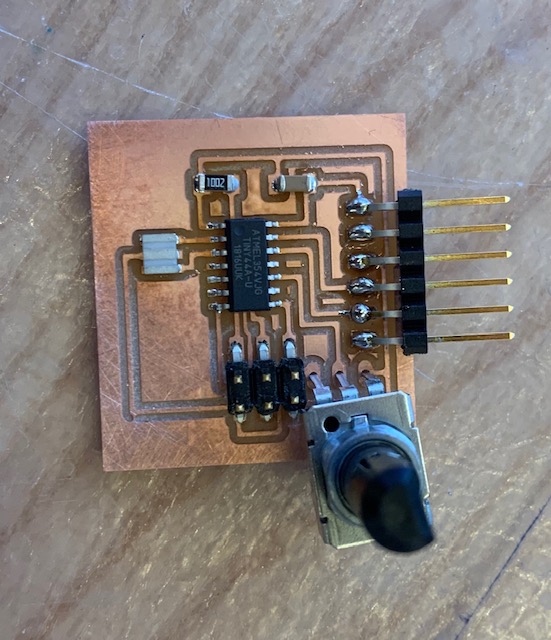
I connected the potentiometer to Pin A3 on my attiny44 and programmed it to send pot values in a constant while loop through the Ftdi.
I used Neil’s hello_world.c code and made a few changes to add functionality for my pot. The first step of all this was reading through the attiny44 datasheet and understanding which registers I would need to change to enable Pin A3 to be an input for pot values.
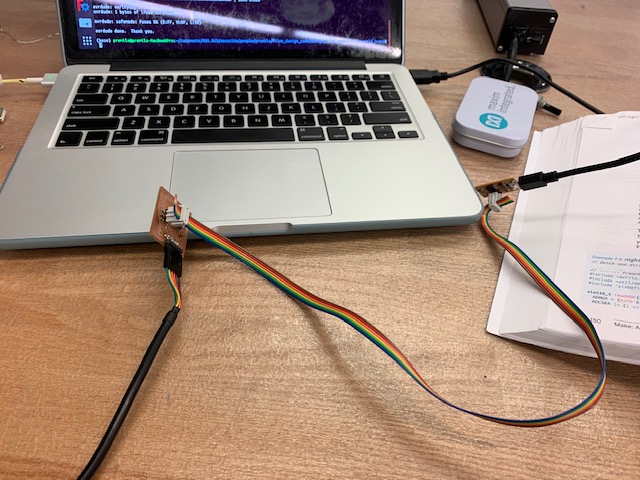
I also made a ribbon cable to make it easier to reprogram the board instead of having to connect 6 separate female headers every time.
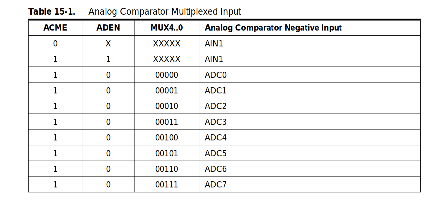
When reading the datasheet, I had to understand how the ADC worked, and how to enable it. The key info is in the Analog Comparator and ADC sections of the datasheet:
Here’s a schematic of the ADC working with the ADMUX:
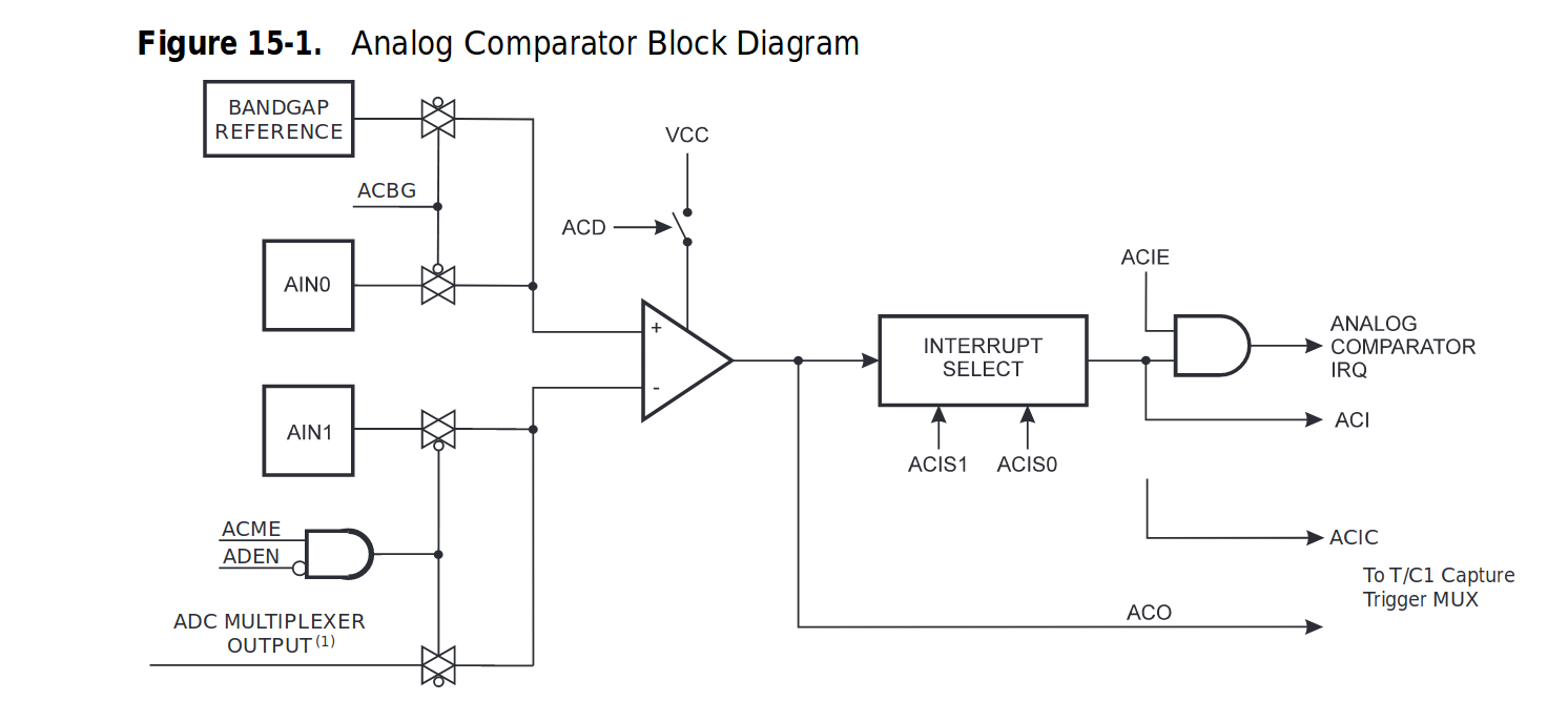
The Analog to Digital converter is configured as single ended input channel so you can select any of the ADC 7..0 pins to replace the negative input to the analog comparator. The ADMUX selects this input- in order to do so the ADC has to be off which means ACME in ADCSRB is set and ADEN in ADCSRA is 0, and then before the conversion ADEN in ADCSRA has to be turned back on in order to use the ADC. Then you can select the correct mux 1..0 bits in ADMUX to select the right input pin on the attiny to replace the negative input to the analog comparator. The pins for selecting the ADMUX input can be found in this table:
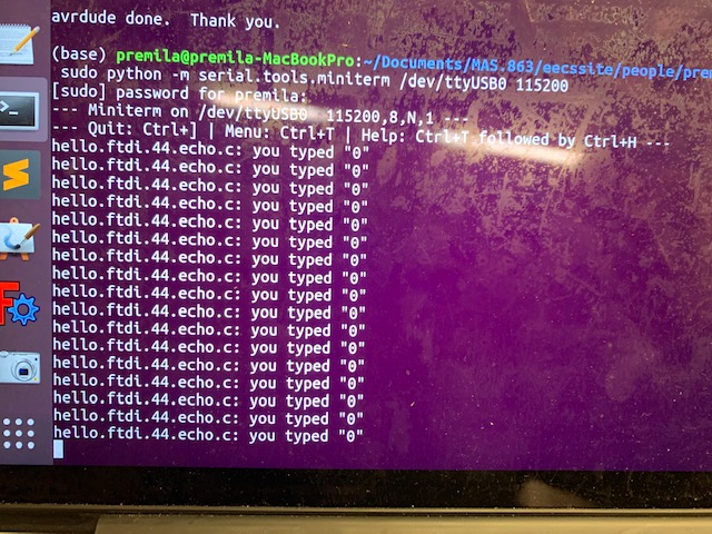
For a long time I was getting on zeros printing out from the pot:
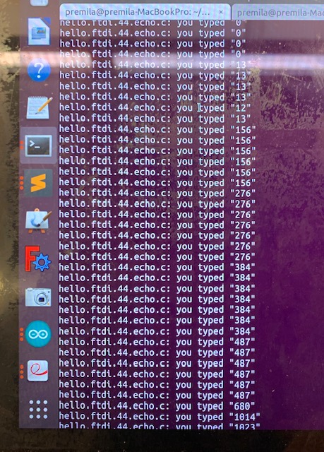
I re-read the data sheet and realized I forgot to re-enable the ADC once I turned it off to change the ADMUX bits. Once I fixed that, it pseudo-worked, and the pot was printing the values 0, 256, 512, and 768 as the pot spun. I then looked at my code again and saw that my readADC() function was not returning anything. I fixed that and then the pot successfully printed values 0 to 1023. I have no idea why the pot would print any non zero values if I wasn’t returning anything, still a mystery I’m trying to understand.
I was able to print values 0->1023, which is the correct conversion for 10 bits from 0->5 volts, as the pot spins all the way around (stretching one resistor fully to stretching the other resistor fully)
I also tested this out in Arduino just for the sake of experimenting. But I found that Arduino is really hard to work with, even just for uploading code, and especially for debugging.
Sidenote, I had a lot of issues with linux permissions and was not able to actually open the serial monitor on my linux machine and had to use a windows/mac to open the serial monitor and see data.
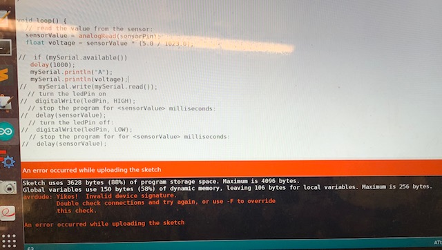
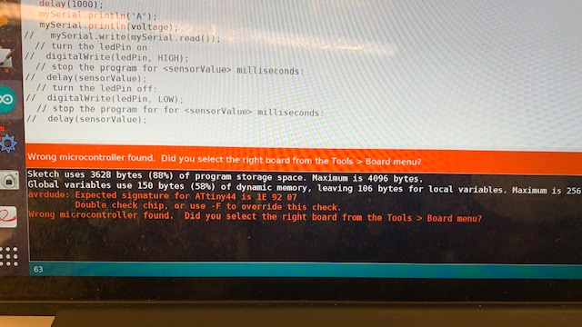
When uploading code, Arduino kept throwing random errors like “wrong microcontroller found” or “invalid device signature”, which I realized were garbage errors because the solution was to try plugging things back in and re uploading several times.
For a while, I was getting garbage data in the serial monitor, all question mark boxes etc., and I realized it was because the timing was wrong. Since I used the make-fuses command and set the external clock to 20mHz, the Arduino environment was not able to use the same clock. I had to take my attiny44 off my board and re solder another one on and then use the internal 1mHz clock on the chip instead, which fixed the problem.
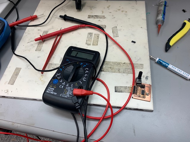
When replacing the chip, I wasn’t so sure about my connections the second time around, so I used a multimeter to check the conductivity between pins and the lines directly beneath them to see if they were connected (if so the conductivity should be low).
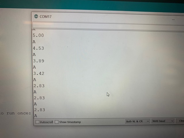
Here’s the successful printout in the Arduino serial monitor for analog pot values ranging from 0->5 volts, which could easily be converted/scaled to 0->1023.