POSTS
Week 9: Input Devices
This week I worked on getting my system to get data from a load cell and make calculations.
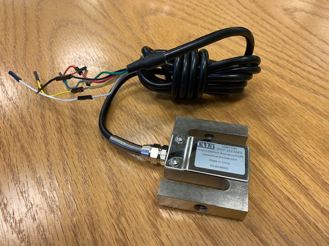
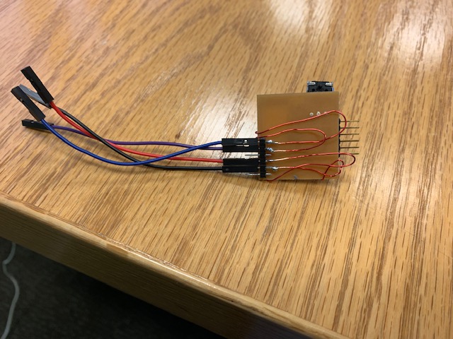
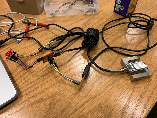
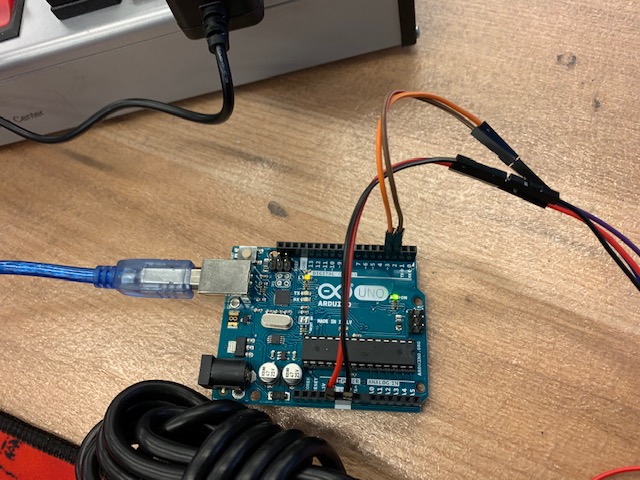
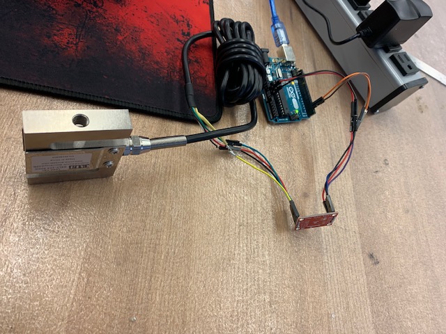
I used a DYLY-103 50 kg load cell and a SparkFun Load Cell Amplifier with an HX711-IC on it. To avoid making a new board since I would likely have to redo everything in the next few days/weeks anyways, I soldered magnetic wires to my attiny44 so I could easily connect to the load cell amp board and then to the load cell. Here’s the whole setup:
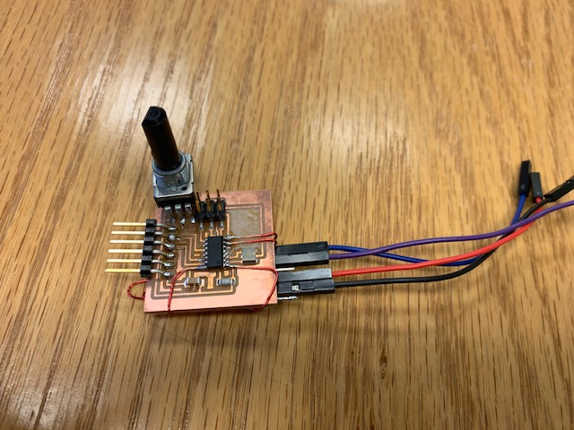
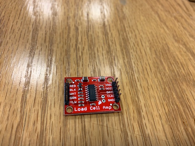
Here’s the load cell amp I used, as well as links to the github repos where you can find example code for using the load cell and load cell amp.
https://www.sparkfun.com/products/13879
https://github.com/sparkfun/HX711-Load-Cell-Amplifier/tree/V_1.1 https://github.com/bogde/HX711
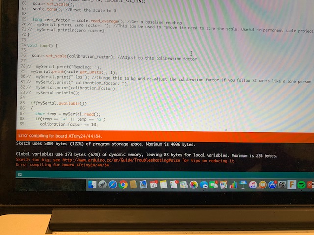
At first I tried using arduino libraries (HX711 has a lot of useful arduino libraries) but the attiny44 does not have nearly enough space (5000 bytes) to utilize those libraries.
Instead of upgrading my chip since arduino was never the long term solution anyways and was rather just to test things out initially, I switched to writing c directly. I still had the same space issues. I had to update the makefile to include certain commands that would optimize how much space I was using and would ignore files I wasn’t using. I still managed to use some arduino libraries here, but I had to manually copy paste the headers and c/cpp files so I could use only what I needed for the sake of space.
This is what the beginning of Neil’s makefile looks like with my edits:
PROJECT=hello.ftdi.44.echo_premila_load_cell
SOURCES=$(PROJECT).c $(wildcard arduino_c/*.c*)
MMCU=attiny44
F_CPU = 20000000

CFLAGS=-mmcu=$(MMCU) -Wall -Os -DF_CPU=$(F_CPU) -std=c++11 -I./ -DRADIO_NUM=0 -Wno-write-strings -DARDUINO=162 -I./arduino_headers -fdata-sections -ffunction-sections -Wl,-gc-sections
I copied over the following header files from the arduino libaries to get my code to work:
Arduino.h
binary.h
HardwareSerial.h
hooks.h
pins_arduino.h
Print.h
Printable.h
Stream.h
USBAPI.h
WCharacter.h
wiring_private.h
WString.h
and the following c/cpp files:
new.cpp
wiring.c
wiring_digital.c
wiring_shift.c
The tricky part is digging through each file and seeing if it requires other libraries that you don’t have yet.
I finally got my code to run, but even after optimizing I still had to delete several strings I was printing to be under 5000 bytes. The long term solution is to use a chip with more space but for now I continued with this.
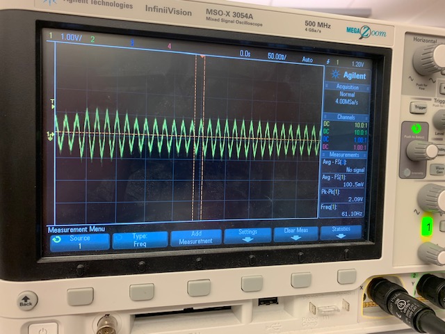
I spent a lot of time debugging the hardware because when I did get the load cell to output data, it was just outputting 0. I use an oscilloscope to probe the system and see where things were going wrong. I noticed as I squeezed the load cell, the signal on the scope was changing in amplitude, so I thought it was doing amplitude modulation, which is problematic because the load cell amp passes 24 bits per clock pulse in for a given load cell value.
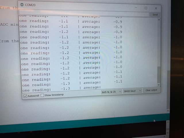
After probing for a long time I wanted to go back and do some more software testing. I used an Arduino uno with my code and with a few minor changes I successfully used example HX711 code to get load cell readings on the arduino serial monitor.
I tried going back to native C and simplifying my code to this:
while (1) {
 if (scale.is_ready()) {
   get_char(&serial_pins, serial_pin_in, &chr);

   long reading = scale.read();

  put_string(&serial_port, serial_pin_out, "Reading: \"");
  serial_putd(int(reading));

  put_char(&serial_port, serial_pin_out, '\"');
  put_char(&serial_port, serial_pin_out, 10); // new line

 } else {
     put_string(&serial_port, serial_pin_out, "Not found: \"");


 }
Unfortunately, still no readings- getting all zeros.
With Ben’s help, I figured out that I was bit shifting the input pins, when the arduino library I was using was already doing that for me.
#define digitalPinToPCICR(p)    ( ((p) >= 0 && (p) <= 10) ? (&GIMSK) : ((uint8_t *)0) )
#define digitalPinToPCICRbit(p) ( ((p) <= 7) ? PCIE0 : PCIE1 )
#define digitalPinToPCMSK(p)    ( ((p) <= 7) ? (&PCMSK0) : (((p) <= 10) ? (&PCMSK1) : ((uint8_t *)0)) )
#define digitalPinToPCMSKbit(p) ( ((p) <= 7) ? (p) : (10 - (p)) )


#define LOADCELL_DOUT_PIN 6//(1 << PA6)
#define LOADCELL_SCK_PIN  7//(1 << PA7)
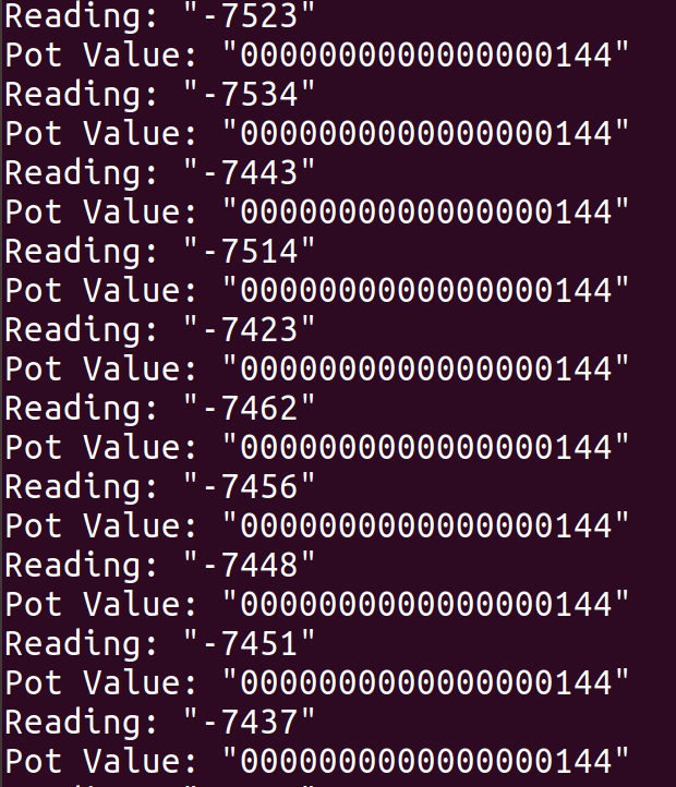
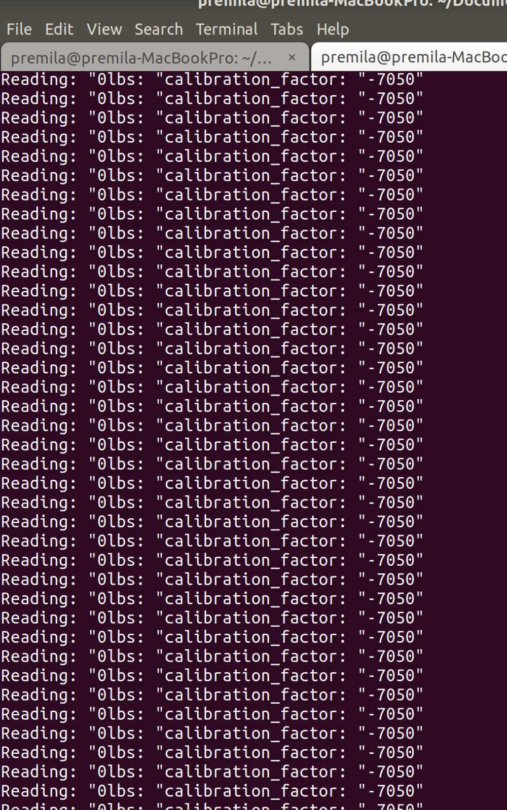
I finally got actual numbers once I fixed this, but the numbers are still a little inconsistent, many are negative and many seem random. So still lots of debugging to figure out.
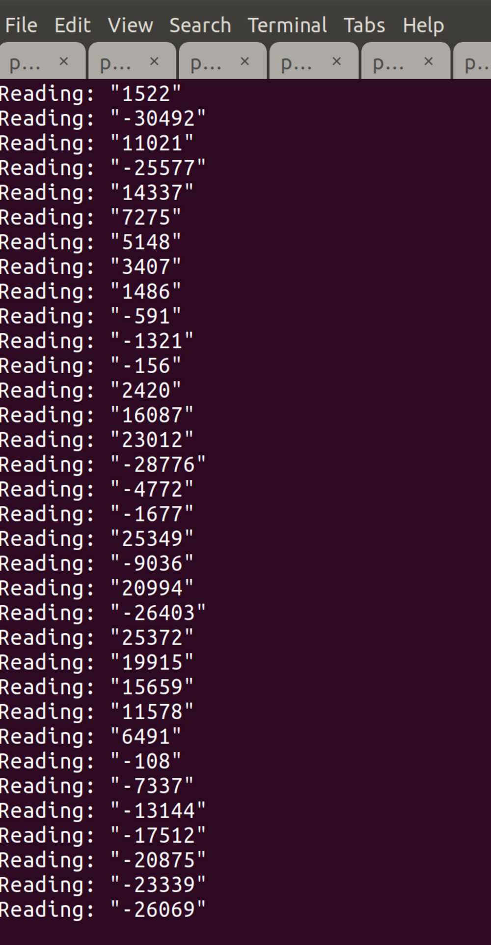
I noticed the values started off all negative (around 19200 lbs?), which I can easily fix by calibrating, but even after applying force using a clamp the numbers were still jumping around.
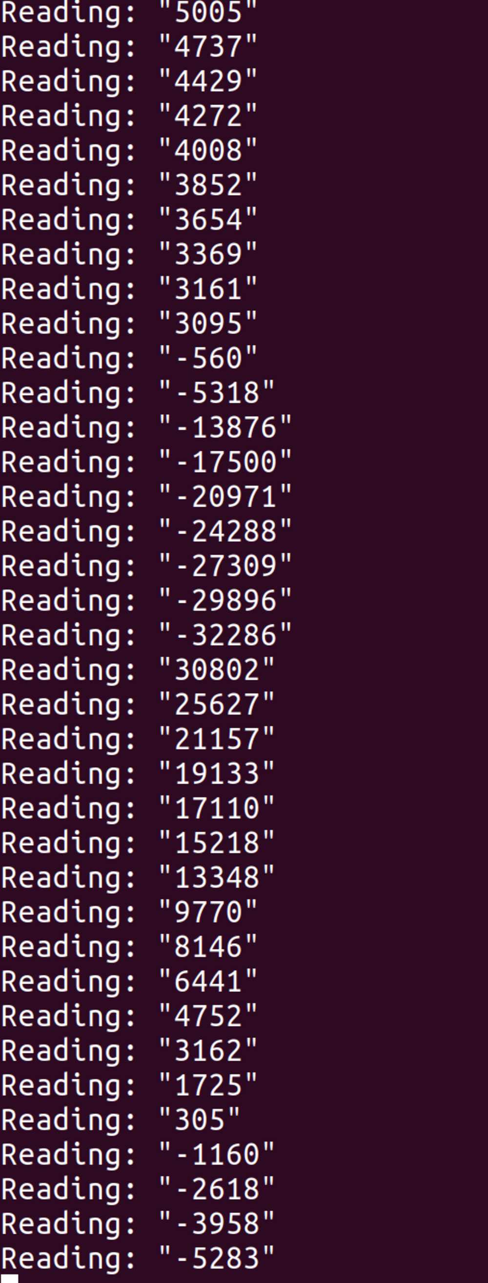
Also still getting negative values even while force is being applied so I have a feeling there’s a signed/unsigned integer error somewhere.
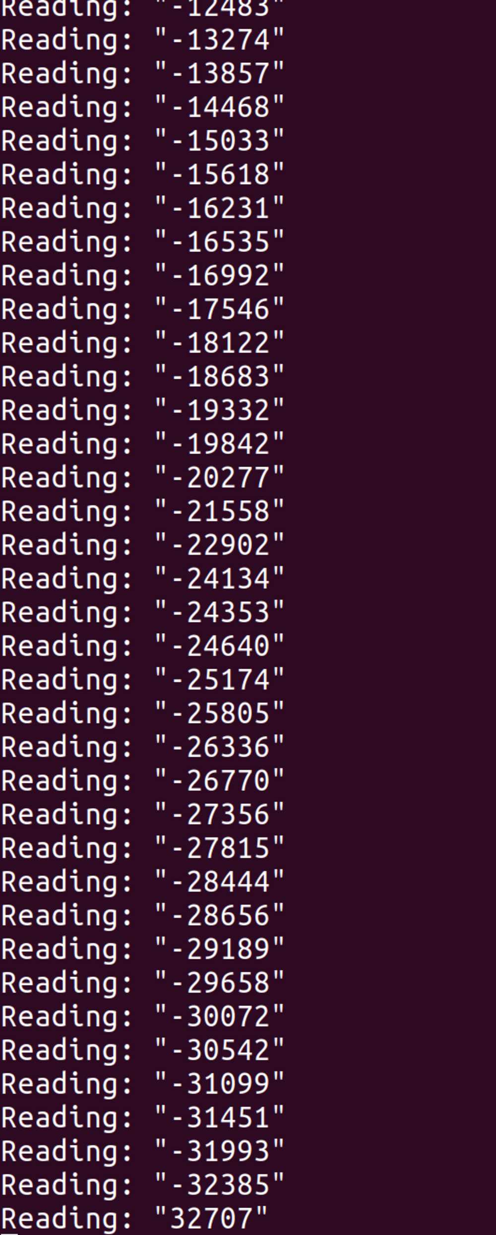
I played around with delays and added some waiting for loops and things looked like they improved but still unclear.
Instead of using a clamp to apply force to my load cell, I placed a weight on top of the load cell and I got really consistent results with that method. So the clamp may have been causing weird effects.
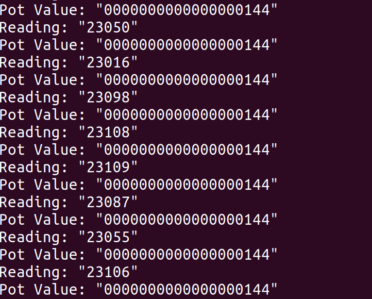
I still need to adjust the calibration because with no weight the load cell returns negative values, but they’re consistent.