week four
electronics design
designing the pcb
The task this week was to redraw the echo hello-world board from past years and add at least a button and LED (with a current-limiting resistor). I used the following hello-world board schematic and resulting traces from past years as a reference in created my own board.
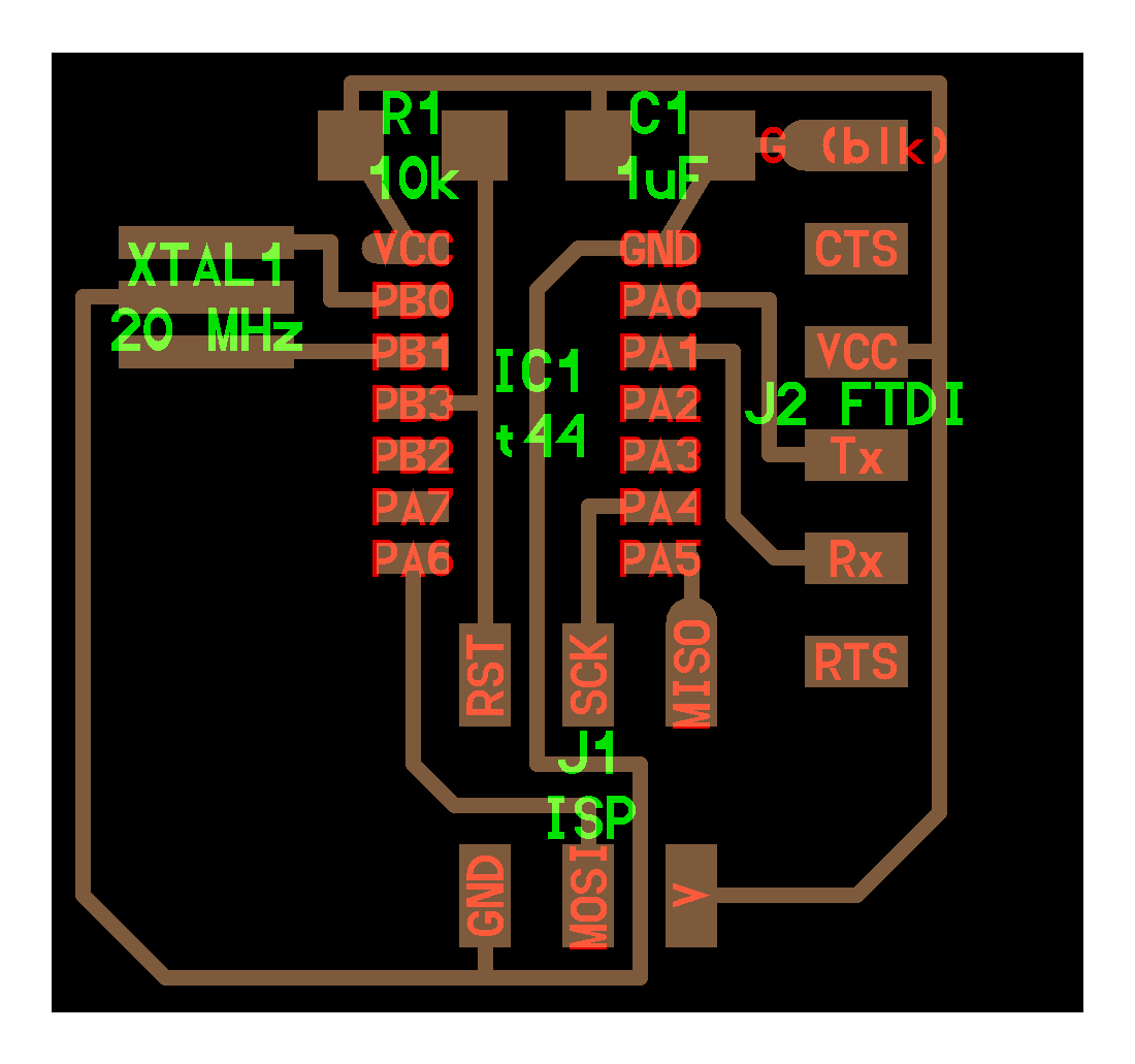
reference board
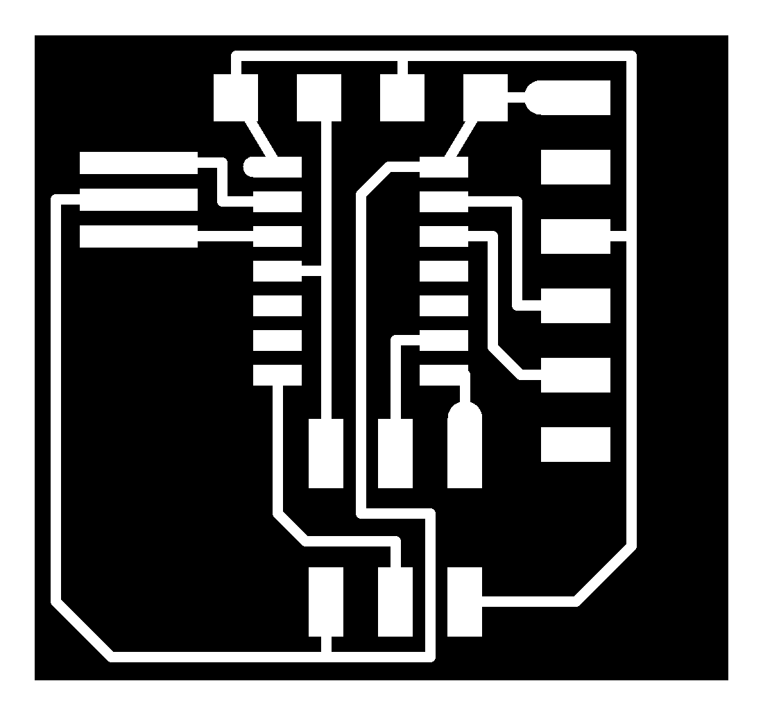
reference board traces
To draw the board schematic, I used Eagle for the first time! After downloading the software, I imported the necessary libraries - the "fab" library, mainly. Then, I was able to search through the libraries to find the components that I needed. This step of the process actually took took longer than expected. The library search bar in Eagle doesn't work very well and scrolling through the numerous versions of all of the component types was quite the process.
When adding components, you can rename, move and assign values to them...well, sort of, not exactly (at least not with some of the components in the fab library). I found it nice to be able to see all of the components laid out neatly before figuring out how to connect them. That makes a lot of sense, but prior to this, I didn't think much on how schematics come before board drawings and how the two differ.
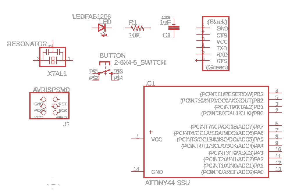
finding components on eagle
After searching, I had all of my components:
1x ATtiny44 (IC1)
2x 10kOhm resistors (R1 R3)
1x 1kOhm resistors (R2): differs from the reference hello-world schematic- this is the current-limiting resistor (pull-up resistor) that connects to the LED.
1x 0Ohm resistor (R4): differs from the reference hello-world schematic
1x tactical button (BUTTON): differs from the reference hello-world schematic
1x LED (LED): differs from the reference hello-world schematic
1x 2x3 pin header (J1 ISP)
1x 6 pin header (J2 FTDI)
1x 20MHz resonator (XTAL1)
1x 1uF capacitor (C1)
Eagle has a netting tool that allows you to draw lines connecting the components. I started by blindly drawing lines, but it quickly got messy and confusing to read as more intersections happened.
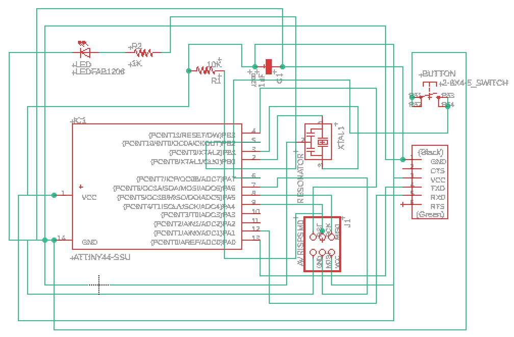
messy schematic
Turns out, Eagle also has a net labeling tool that allows you to draw shorter lines from the components and label the line endpoints. Matching net labels correspond to connections made. This was so much better :)
clean schematic (using net labels)
Finally switching from schematic mode to board mode, I was able to orient the components as I saw fit. Eagle has to way of letting you know which components have or have not been connected, which was useful in checking my work.
At some point in the process of connecting components, no matter how much I moved pieces around, I wasn't able to make a connection without intersecting already existing connections. To help with this, I added a zero-resistance resistor (R4), which allowed me connect the button to PA7 on the ATtiny-44 and finish the schematic.
When I orginally made the board, I was using the Eagle default in terms of line thickness. According to Anthony, this would not work for milling purposes. We changed the line thickeness setting to 16.
As a finishing touch, I used the text tool to write my name and MAS.863. For some reason, the line thickness I set for the nets didn't translate to this...
redrawn board
I exported the board as a black and white .png in SUPER high resolution - 1000ppi - and threw it into Adobe Illustrator to make the outline.
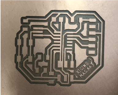
redrawn board traces
The shape of my board looked a bit like a milk jug to me, so I went with it. I'm lactose intolerant, too, so it's ironic.
inscribing traces within milk jug outline
It was slightly confusing to me how the Roland mill reads mods to cut. I originally had inscribed the traces within a milk jug outline, thinking that I could just use the outline. This is not the case. The software reads where the picture transitions from "black" to "white," and then cuts on the black side.
Basically, the areas of the milk jug that I wanted to keep were colored solid white and the areas that were to be cut out were colored solid black. To orient the traces correctly within the milk jug, the rectangles in which the milk jug and the traces were inscribed needed to be the same size.

final milk jug outline
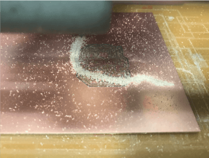
Using the Roland mill and mods>programs>open server program>Roland SRM-20>PCB png, I milled the traces. Instead of using the default of ~1000dpi, I used 2000dpi instead. This ensured that the files would cut to original scale.
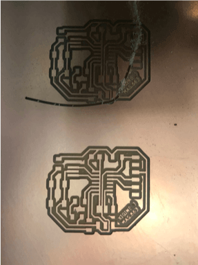
milled traces
As seems to be a common theme in my class experience, I done goofed :( While preparing to cut the milk jug outline, I forgot to adjust the dpi to 2000. I also didn't check the actual mm/in of the job before running it. As a result, the outline cut into the traces and I needed to start over.
goofed outline
NOTE TO SELF: CHECK YOURSELF BEFORE YOU WRECK YOURSELF - don't just look at the cutting settings and assume mods will auto-scale your image. check things like the image dpi and dimensions of job, too.
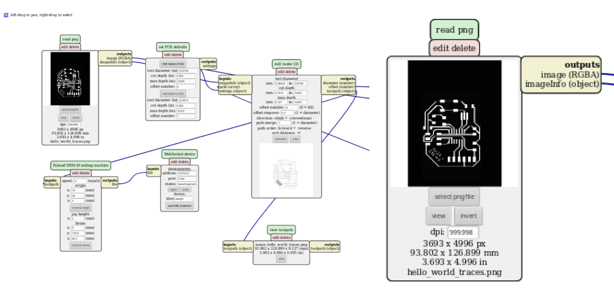
incorrect mods settings
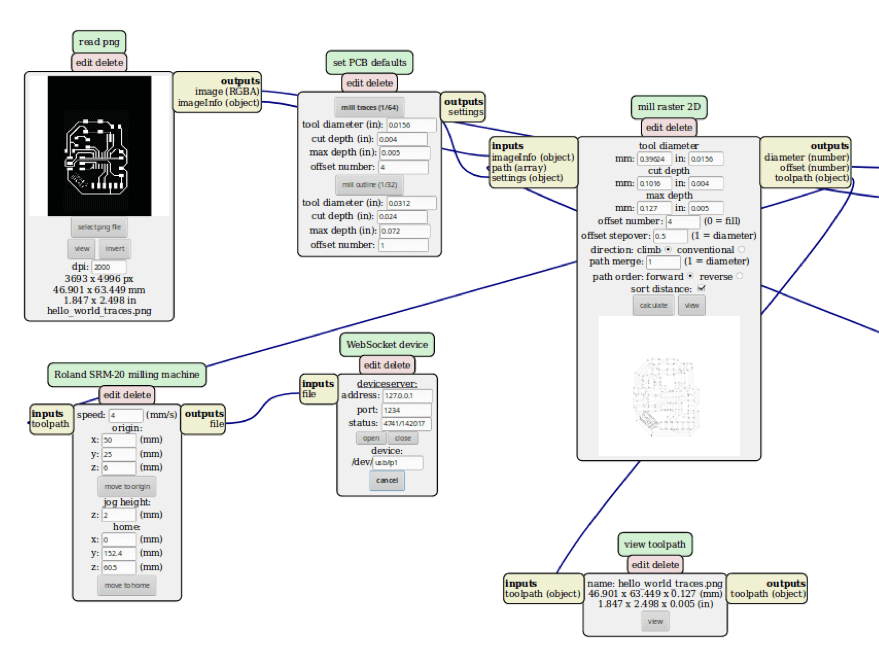
correct mods settings
The second time around, the milling process went relatively smoothly. At the very end of the outline job, when the handle was being cut out, the already-cut milk jug board lifted from the platform and got caught on the bit. Retrospectively, this happened because I didn't not tape enough underneath where I was trying to cut. NOTE TO SELF: tape enough under where you're trying to cut. Thankfully, the handle had mostly cut out by the time the board got caught, and I just had to finish the final layer of the handle with an X-acto knife.
milling traces a second time
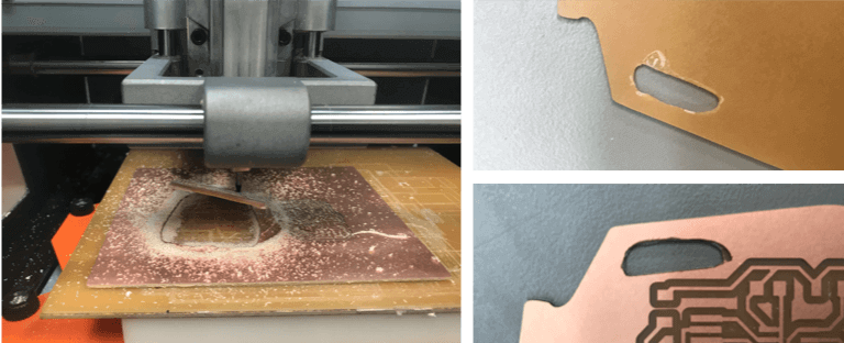
left: board caught on milling bit; right: handle finished with x-acto knife
I noticed that there was very obviously a pad that was connected to a net that should not have been there. I cut away at this with the X-acto knife. This is where I made another mistake (to be explained later).
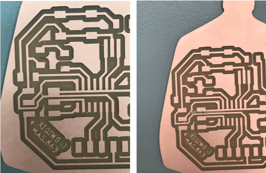
left: traces not cut cleanly; right: fixed traces by x-acto knife
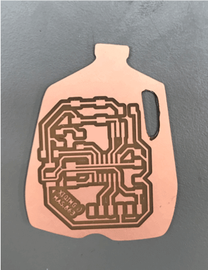
"finished" milled board
I found all of the pieces that I needed and started soldering. Perhaps due to practice, soldering components onto this board was easier and went faster than the soldering that happened during week two.
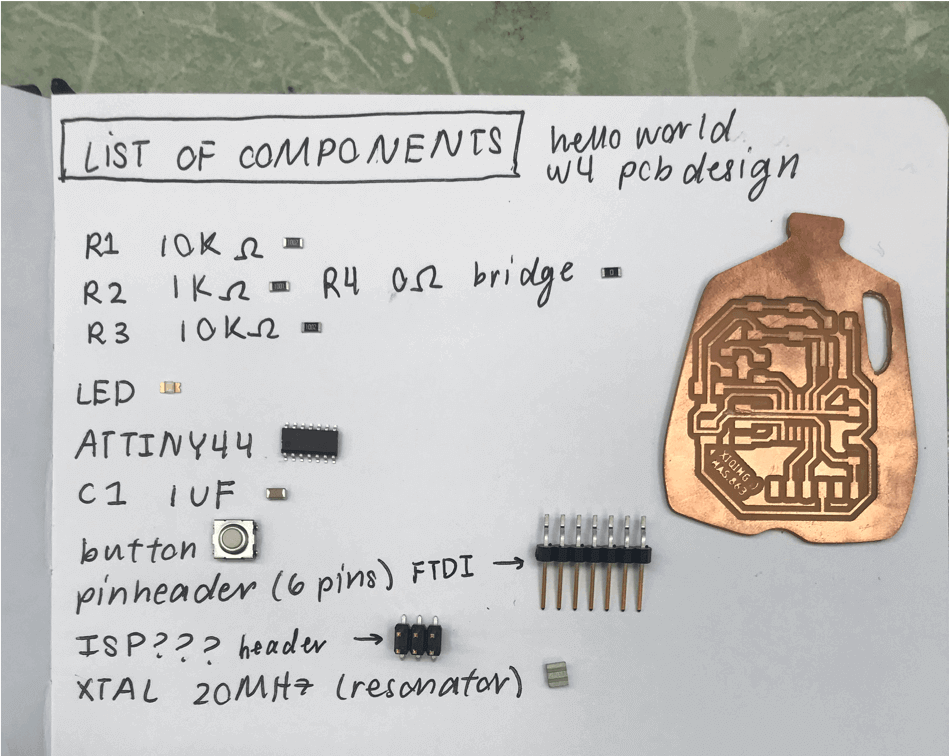
components used
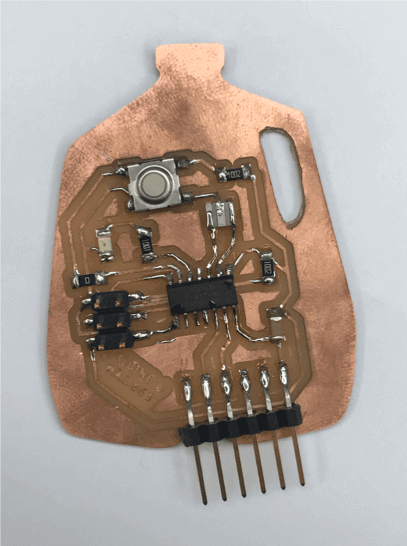
all components soldered
With the board soldered, I went to testing its function. This was unsuccessful. After testing for shorts with a multimeter, I discovered many shorts around the 2x3 pin headers that Anthony predicted originated from the pads on the left side of the ATtiny44.
As also seems to be a motif of this class, Anthony was exactly correct. After lifting the ATtiny44 from the board, I realized that there was a whole LINE of shorts happening. Though I had previously fixed that one pad that hadn't cut from the net, I had also completely overlooked the whole left side of the ATtiny44 pads that were connected to that same net.
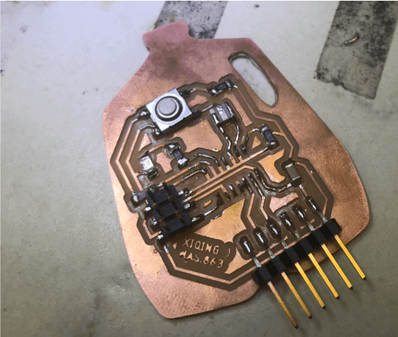
a whole line of shorts
After cutting the pads away from the net and resoldering the ATtiny44, I was finally ready to program. I didn't bring the programmer we made during week two, so I opted to use the Atmel-ICE programmer (white box). Additionally, I found the correct hello world make file to upload code (for me, this was the ATtiny44 make file). Anthony helped me through most of the code uploading through terminal.
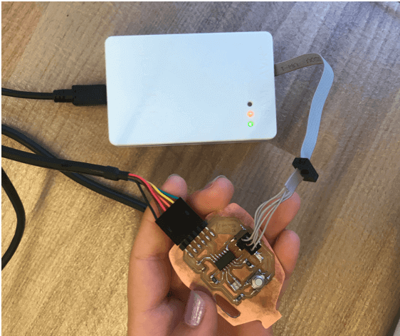
hooking up to the programmer
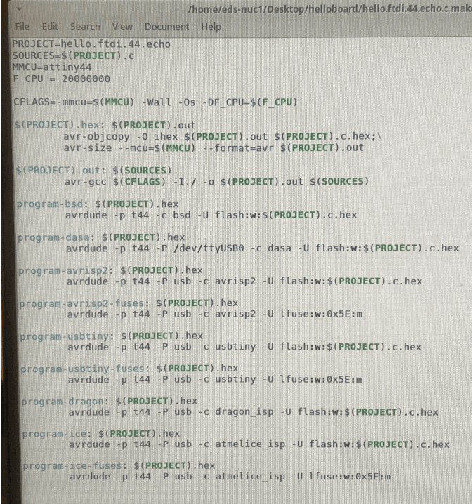
hello world attiny44 make file
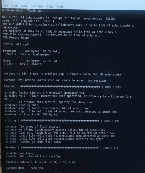
program-ice
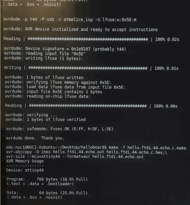
program-ice-fuses
After programming my board, I opened Arduino's Serial Monitor and switched to 11520 baud, since that's what this board runs on. I could then type a letter in the input box and string together a message.
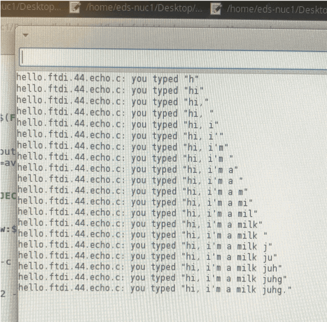
testing the board
In summary, it was super cool getting to experience the whole cycle of pcb design, production, and programming. And (arguably most importantly) the milk jug sparks a little bit too much joy!