week five
computer-controlled machining
brainstorming for something big
The assignment for this week was to "make something big." Like, anything. As long as it's big. And its pieces, laid flat, fit on a 4'x8' sheet of oriented strand board (osb) of ~7/16" thickness.
oriented strand board (OSB)
Osb is not *the worst*, but it definitely has its limitations. It was recommended not to make thin features smaller than 2" (by width). Also, using osb narrowed the scope of "big" designs to those that could be constructed using 2D pieces only.
With osb in mind, I comtemplated a couple designs. The first was a simple chair:
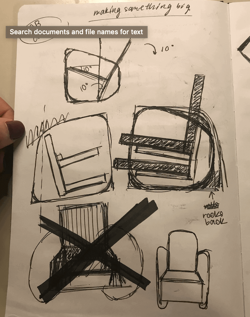
chair design
The second was a bookshelf that could double as seating or stairs. This required more pieces and was slightly more complex:
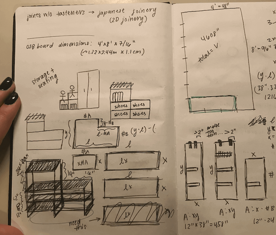
shelf design
This seems like a motif of this class, but somehow I always flesh out ideas and then completely abandon them when it comes down to the wire for simpler, easier designs that, at the end of the day, I end up liking more. I was browsing around on Youtube and found this diy lamp video that I took inspiration from.
The lamp in that video is hand made from plywood and light rods. It looks super slick and finished. But, because we only had osb, I used the same pressfit principles but changed everything else. The only thing you really need for a lamp is something that makes light and some panels to attach that something to.
I decided to make a double-stacked hexagonal base, with three places that the legs/structure of the lamp could pressfit into. Rectangular panels could slide into cutouts in the legs that I could later stick leds on to complete the lamp.
The lamp design was simple, and due to the dimensions that I wanted for the lamp, the pieces only took up half of the alotted osb board. So, I decided to tweak a couple demensions - the legs and the panel length, mainly - to make a slightly differently shaped lamp.
cad/cam for the lamps
I used Solidworks to parametrically design the pieces of the lamp. This allowed me to design in 2D and see how those pieces would fit together in assembly. Designing parametrically made my life a lot easier later when I needed to change the overall height of my lamps.
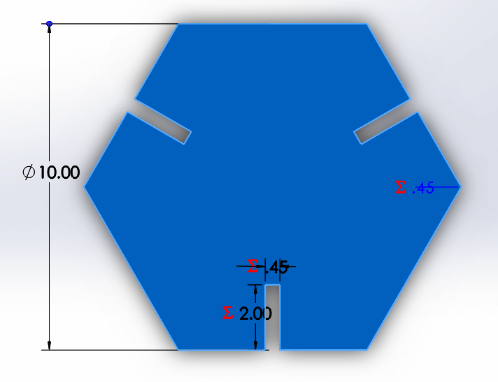
hexagonal base, panel/shade piece, press fit vertical supports
lamp assembled in Solidworks
At the end of the CAD process, I placed all of the pieces within a 4'x8' rectangular outline to make sure everything would fit on the sheet of osb alotted. To my surprise, the lamp pieces actually didn't take as much material as I had originally expected, and I ended up being able to make two lamps - one taller than the other but with lamp shades of a shorter length.
lamp pieces laid flat in Solidworks
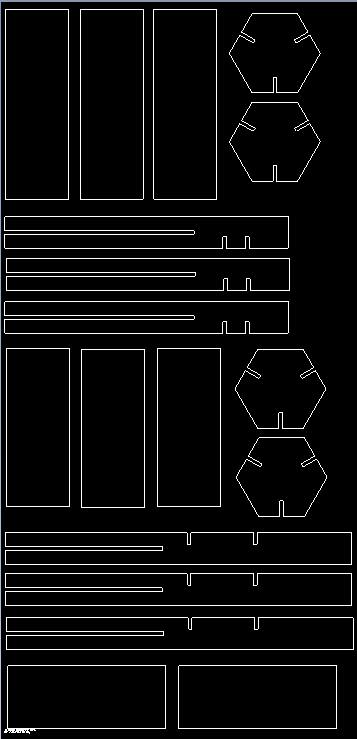
.dxf file of the flat lamp pieces
Anthony helped me through the CAM process using Solidworks' built-in CAM functions. We had to first indicate where the corners of each press fit joint were, and then figure out the machine toolpaths to make sure that the job would run correctly. Something to note is we added in tabs (a built-in tool) to the pieces so that they would stay in place while the milling happened.
machining the lamps
videos:machining osb lamp frames
Finally, I was ready to mil. For this project, we used the Onsrud CNC mill in the Architectue shop.
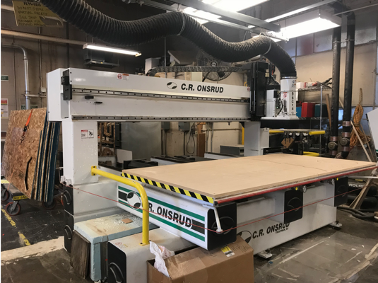
Onsrud CNC mill
The Onsrud CNC mill was an interesting machine to watch. It used air suction to keep the osb sheet stuck to its platform. It also has an automatic tool changer.
During the actual milling process, the tool first drills holes in all of the press fit corners that we previously mentioned had been separately marked during the CAM process. Then, it begins cutting the pieces out. The whole process was quite fast - the machine absolutely ripped through the osb.

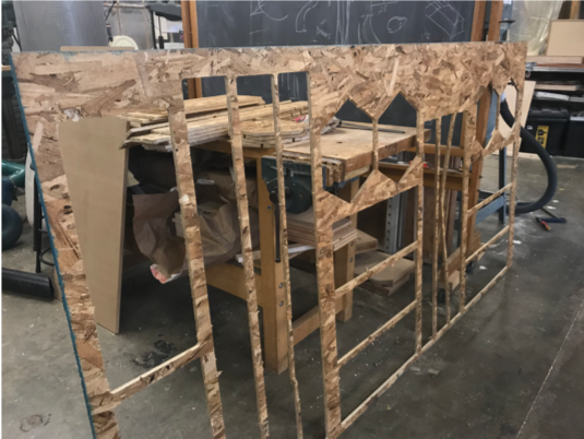
finished running job on Onsrud
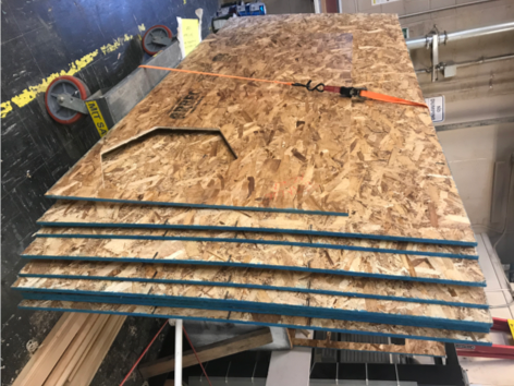
After the job finished, the pieces were still somewhat stuck to the rest of the board via the tabs we had added in during CAM. However, they were pretty easy just to snap off.
osb post-milling
Because I snapped of the tabs, in addition to the general nature of osb, the pieces came out pretty rough on the edges. An easy fix for this was just running the edges along a bandsaw to get rid of any excess material and burring.
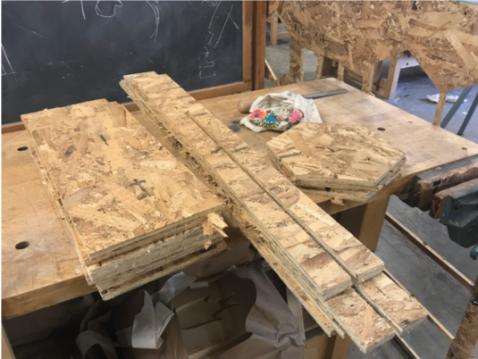
osb pieces
lamp assembly
Finally, I was ready to assemble the lamp frames. In the midst of muscling my way through it, an architecture staff member told me it would be much easier to use a hammer. Go figure.
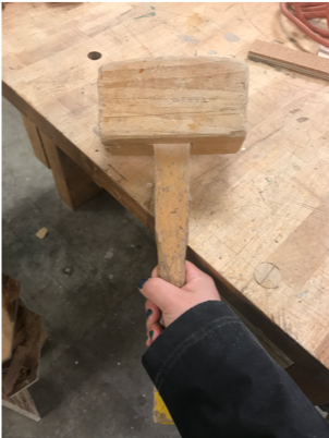
wooden mallet
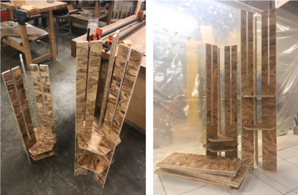
assembling lamp
The longer pieces with slots press fit into the hexagonal base pieces. The flat panels then slide into those slots to create the outside of the lamps.
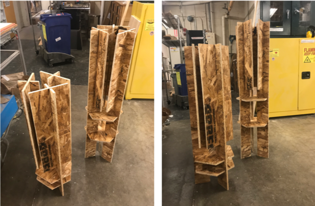
finished assembling lamps
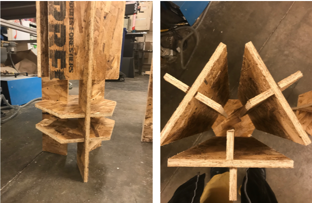
lamp features
finishing lamps
Now that my lamp frames were assembled, I needed to turn them into actual working lamps. I purchased some LED strips which could be cut at the copper notches you see in the pictures and soldered together.
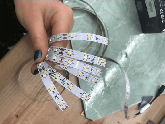
cutting led strips to length
After cutting the LED strips to the lengths that I needed (two for each flat panel of each lamp), I worked on prepping them for soldering. There was a film over all of the copper pads, so I first scratched them to expose the shiny copper underneath.
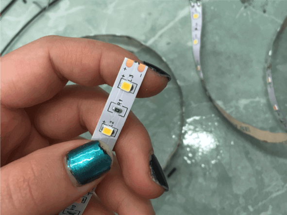
copper pads before scratching
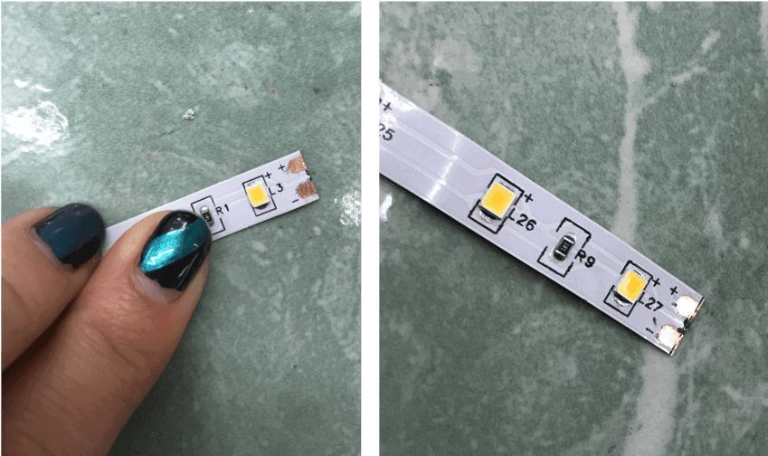
shiny copper exposed and ready for soldering!
I soldered the strips together making sure to algin + and - terminals correctly. Then, I hot glued these strips to the inside of the flat lamp panels and was ready for light!
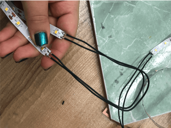
soldering led strips together
let there be light!
videos:lamps, finally completed
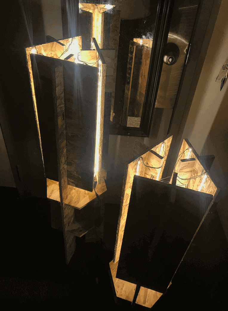
finished lamps!
I'm quite excited about th eway these lamps turned out. They create a cozy ambience and bring warm, pretty light in lieu of the dull pre-installed lights in my dorm room.
brief notes on the onsrud
the machine self compensates so there is negigible kerf
use the 1/4" for traces and details and the 3/8" for the outline
you can't get a 90 degree corner with a round tool
runout = when bits are secured and turn, they flare out a bit (which is called runout)
spindle speed = how fast does the tool spin around (in rpm)
feed = speed that the tool moves in the XY
plunge = how fast the tool lowers (moves/"feeds" in the Z direction)