week nine
output devices
deciding on an output device
For my final project, I wanted to incorporate a speaker system to allow users to play music for maximum ~relaxation~ and set alarms in case they were planning on sleeping while in the spa box.
In order to create a speaker system, I needed a couple components - audio input, an amplifier board of some sort, and audio output (speakers). The process of understanding and making this system actually took much longer than I had originally anticipated.
making the amplifier board
After asking Anthony a bunch of questions about amplification systems, I learned that I would need to use some kind of audio power amplifier. The EDS only had the LM4681s (1.1W Audio Power Amplifier with Shutdown Mode), so I used the typical application circuit given on page 2 of its data sheet to sdtart my schematic and board in Eagle. You can find the LM4681 data sheet here.
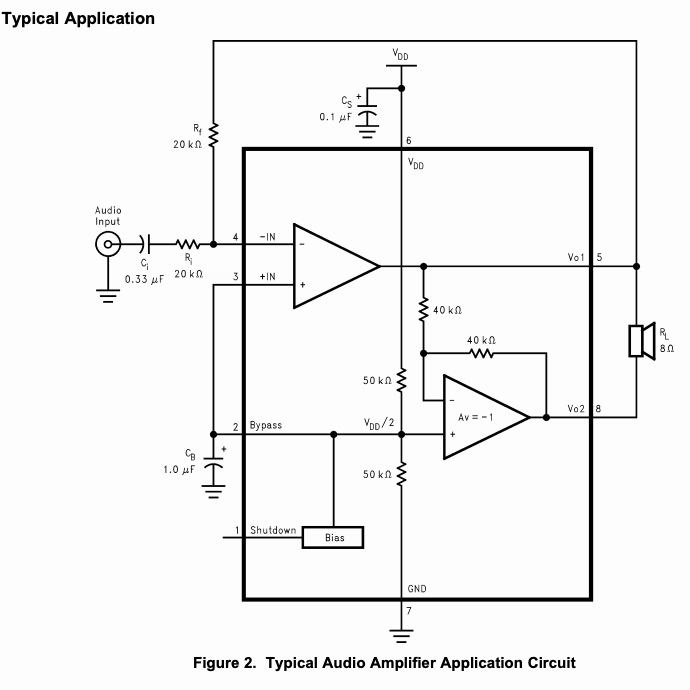
typical application circuit pulled from LM4681 data sheet
I ran into my first issue pretty quickly. Anthony showed me the SnapEDA site, which is super useful and has downloadable Eagle traces for a lot of different components. Unluckily, the LM4681 is not one of these. So, I needed to draw the trace myself. In Eagle, there's a way for you to create new libraries that will contain 3 parts of information - footprint, symbol, and device. Anthony helped do this one, but I took notes for future use! The following is specifically for the LM4861, but can be applied to any part - here's how this works:
1. in Eagle, navigate to control panel > new > library
2. making the footprints
adjust grid to be the the size of the pitch (between the pads of LM4861)
place pads (size pads correctly based on data sheet)
draw on layer 21 tPlace (this won't show up in copper/on traces, just allows you to mark and outline part, add name, etc.)
3. making the symbol (this is what will show up in your schematic (so, measurements don't matter)
name the pins
mark pin1 with dot, circle, whatever
add name to symbol
4. making the device (this is what maps the pins and traces of the footprint and symbol to each other, so it's ABSOLUTELY CRITICAL to CONNECT CORRECTLY)
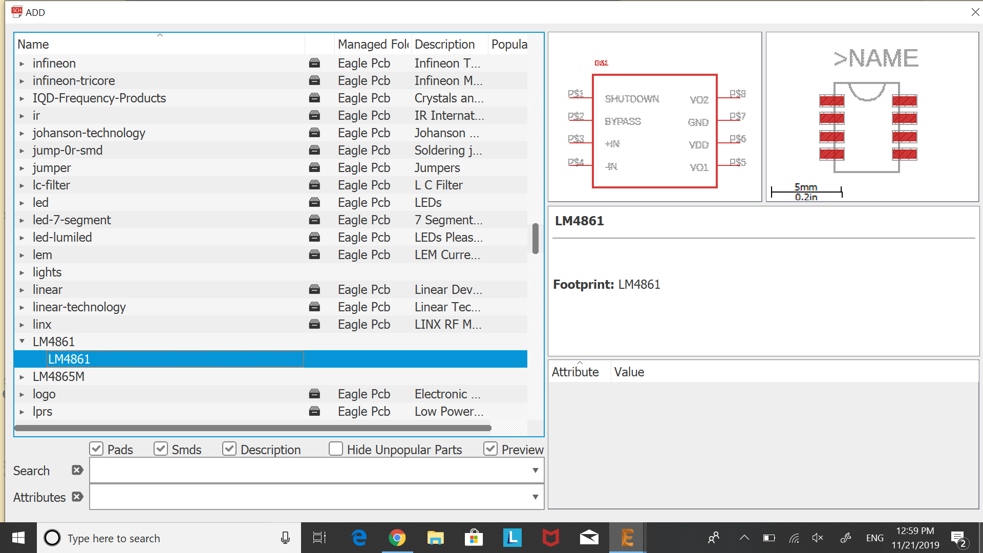
new LM4681 Eagle library
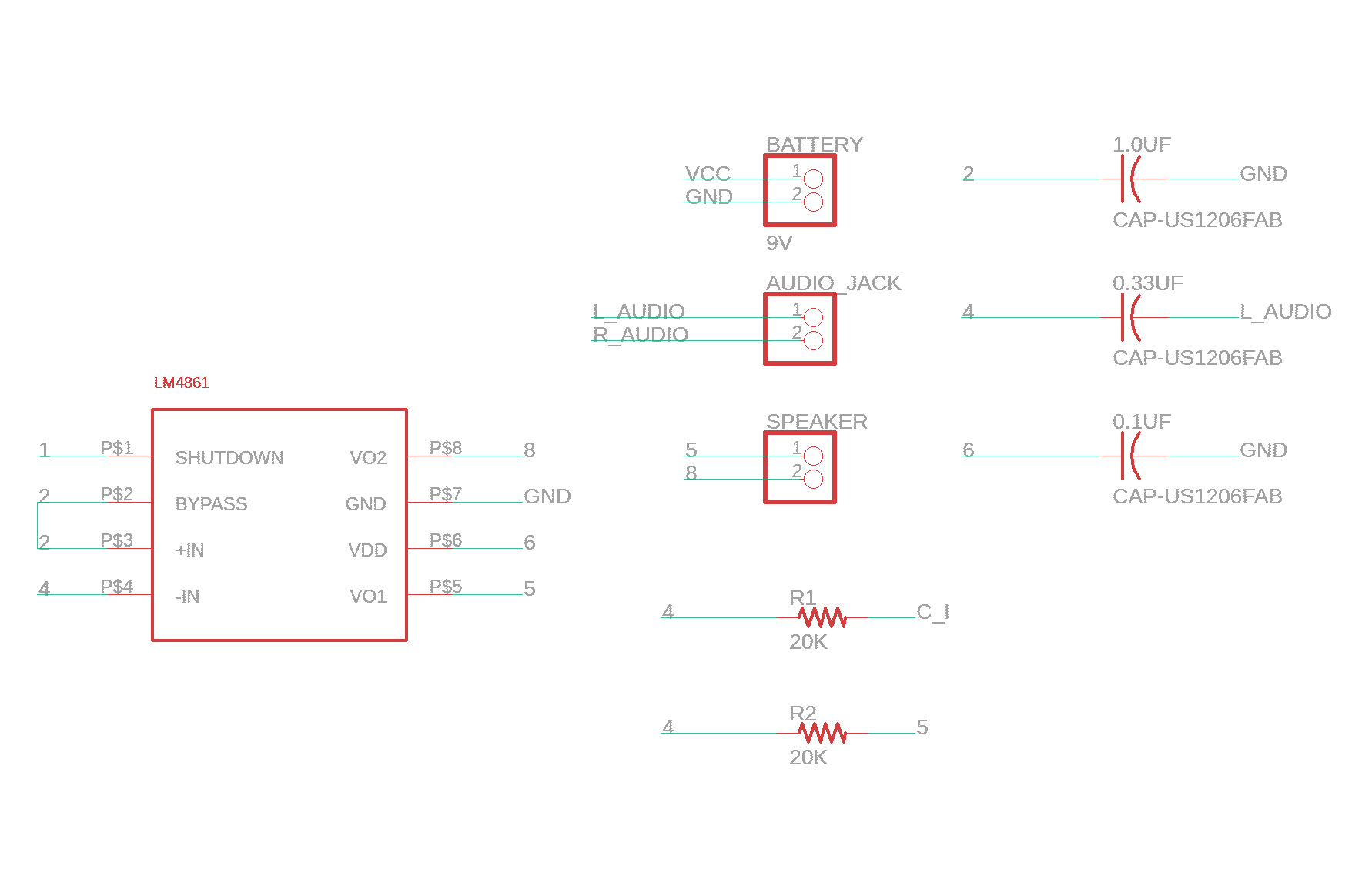
finished amplifier schematic for left speaker
After finishing the schematic according to the typical application circuit, I realized that the circuit given is only for one speaker. Since I wanted to have two speakers in my final project, my board would need to have two LM4681 amplifiers (meaning 2 copies of the typical application circuit).
Something I also needed to think about was what kind of connection would happen at the audio input. Because I wanted users to be able to hook up a device of their choice to my system, I opted for a barrel jack and aux cord set up. This meant a barrel jack trace would need to be placed and connects where audio input connects to C_i and R_i in both of the two amplification circuits I was using.
Much Eagle-ing happened, and there was quite a bit of debugging that happened along the way, but eventually, I was able finalize the traces!
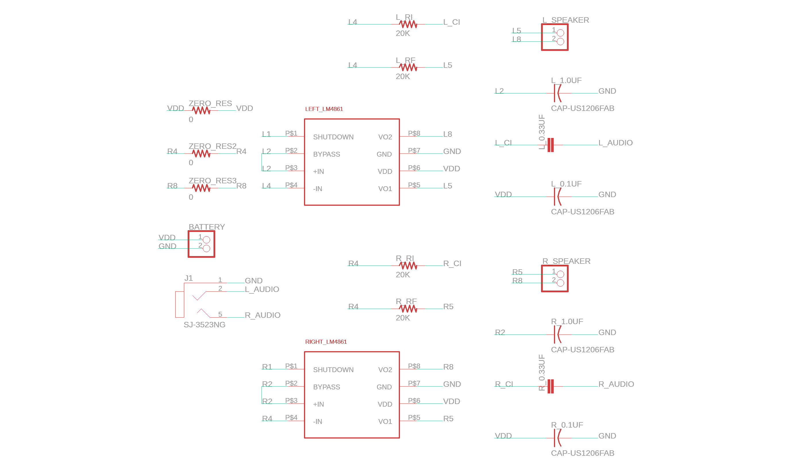
amplifier schematic in Eagle
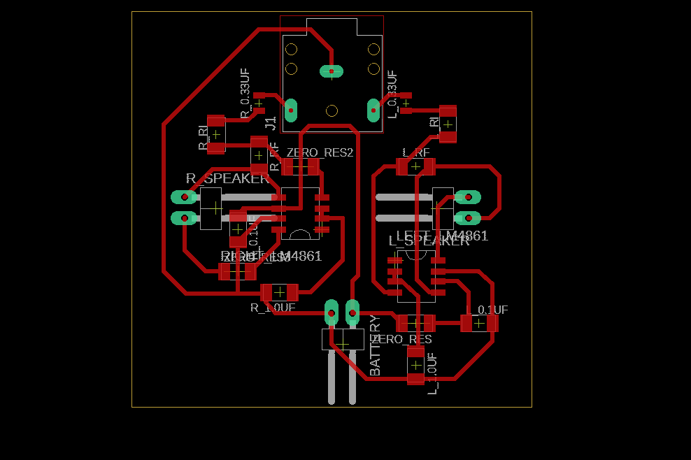
amplifier board in Eagle
I decided to use the Other Mill (it's literally called the "Other Mill") instead of the Roland, since I was perfectly fine with a rectangular shaped board. All you need to do is adjust the yellow bounding box around your traces while in board mode. The Other Mill will take files directly from an Eagle .brd file, which is super nice, and your board shape will be whatever that yellow bounding box looks like.
Instructions on milling with the Other Mill for my own safe keeping:
1. Secure copper plate onto platform with double sided tape.
2. Placement > make sure to have enough margin (I used 15mm in the X and Y directions).
3. Tools > 1/32" PCB conservative and 1/64" flat end mill
To physically change out tools, use the two wrenches that come with the mill
The 1/64" flat end mill is just for milling out small portions (pretty quick process)
The 1/32" PCB conservative is for most of everything else (conservative means you'll break less tool bits)
4. Choose and locate tool in the software.
This should be automatically done by the machine, but make sure that the tool is above the METAL PLATFORM befor pressing locate tool. I was trying to locate tool on the surface of the copper plate once, which 1) doesn't work and 2) is very incorrect/bad for the tool bit.
5. Make sure all door panels are on - there are 3 (I've previously wondered why my job wasn't running, because I didn't realize there were side panels) - and run job! You'll be prompted by the software to switch out the 1/64" bit when the time comes.
videos: milling amplifier board with the Other Mill
The Other Mill is just way less finicky than the Roland (especially since there's a bit of a door sensing issue with the latter). Long story short, let's just say that ever since milling this amplifier board, I never went back to using the Roland.
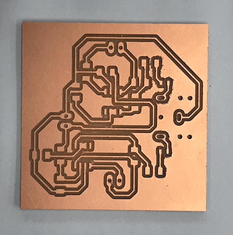
first milled amp board
The board milled smoothly, but after consulting Ben, we realized that the pads of the barrel jack had through holes with not enough copper around them. this would not allow me to make very sturdy connections. Additionally, I needed to use 0.33uF capacitors, but these do not come in a size that matches the Fab1260 resistor trace I had used for all resistors in my board. So, it was back to Eagle-ing...
I switched out the trace where the 0.33uF capacitor needed to be with the 0805 resistor trace (it's much smaller). For editing the pads of the barrel jack trace: similar concept to when we were making a new library for the LM4681, but now, I was just editing the pad sizes of an existing trace (which Eagle has some presets for). Instead of "auto" (lol), I used 56 for the pads. This seemed to do the trick.
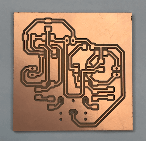
I milled the board a second time, and voila! The pads for the barrel jack now have more copper for me to solder the pins to.
milled board with larger pads
It was finally time to solder my amplifier board. I gathered the necessary components and laid them out to make sure I wasn't missing anything:
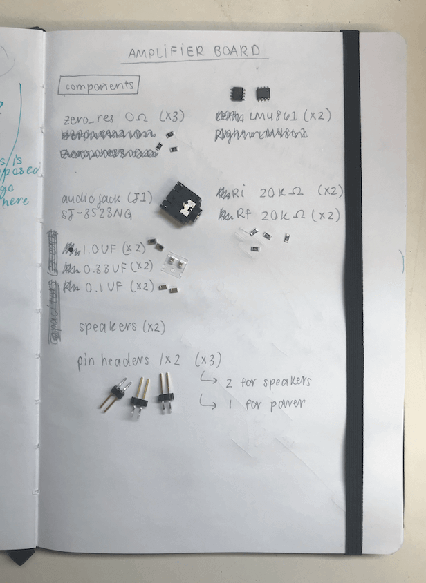
components for amplifier board
The LM4681s run on 5V and are only rated for 1.1W, so my speaker options were limited. Anthony found two speaker options for me - a 0.25W speaker and a 0.5W speaker - which I soldered pins/wires to and tested out. The 0.25W speaker is on the fab lab inventory and is the Mallory Sonalert Products Inc. 8 Ohms General Purpose Speaker 250mW 900Hz~6.5kHz Top Round 81dB (cick here for data sheet). Because at this point in time, I didn't have my main board made (from which I was planning on connecting the amplifier board), I tested the board using a power supply at 5V. It worked! I was super excited about it :)
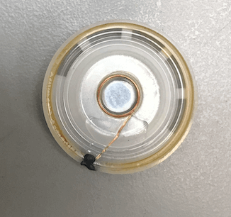
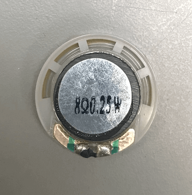
0.25W speaker
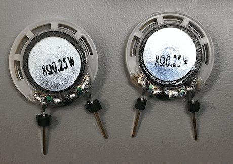
soldered pins onto 0.25W speaker
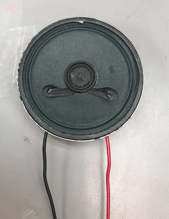
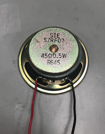
0.5W speaker with soldered wire connections
videos: testing speaker system
The larger 0.5W speakers were definitely louder, but I wasn't able to use those in my final project because the EDS only had one of them. That being said, the smaller 0.25W speakers are loud enough for the purposes of my spa box (if you turn up the volume up on the device connected), so it worked out in the end!