week final
making the spabox
spabox, a portable spa experience
inspired by the screaming chamber, spabox is a box you can stick your head in to block out the outside world with scents and soothing music, etc. (like a carry with you spa)
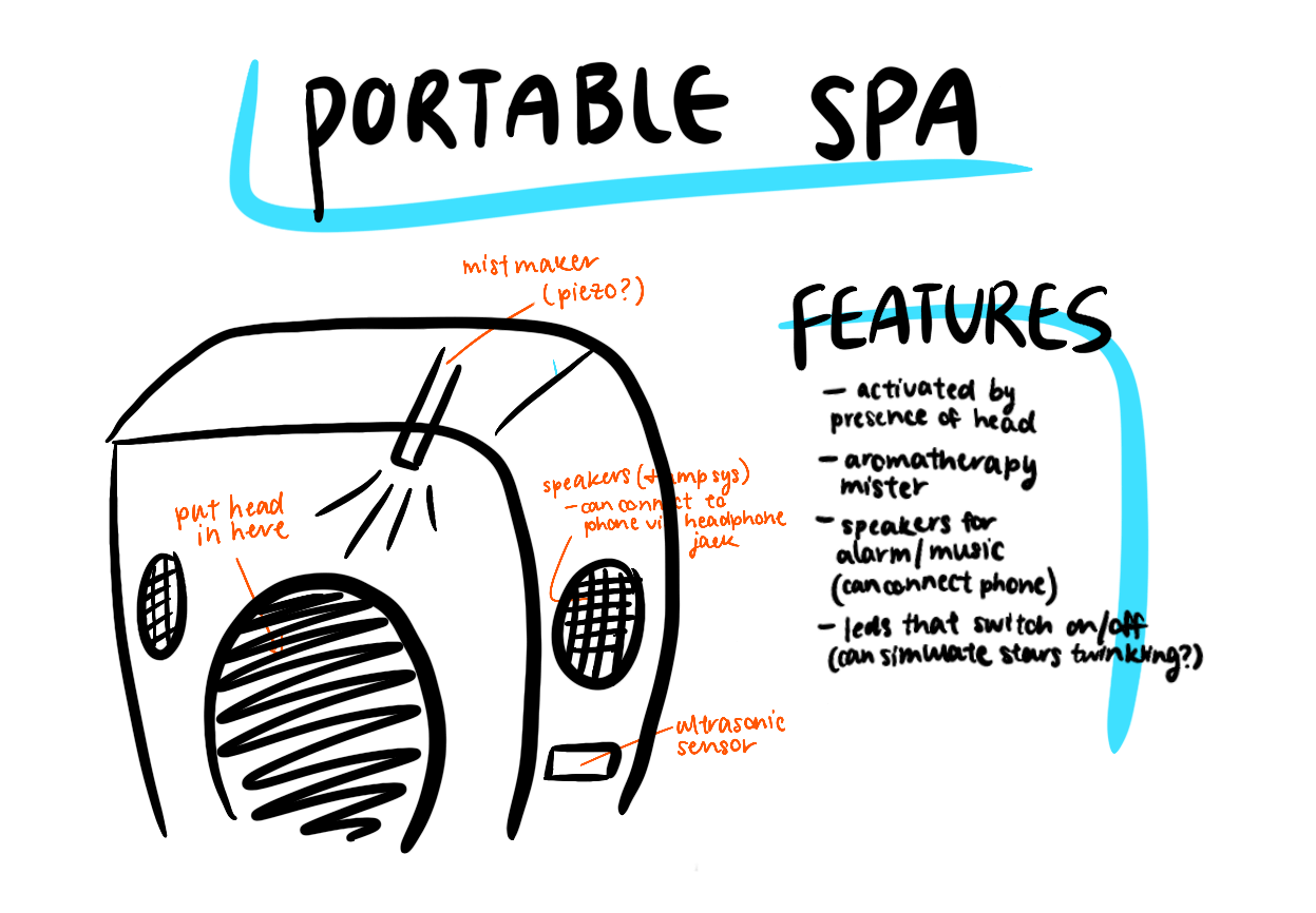
final project idea - a portable spa
skills used
making the main circuitboard
The first actionable was making the main circuitboard from which my other systems (ultrasonic/piezo mistmaker and speaker system) would be powered and controlled via an ATtiny44. I admittedly didn't have much criteria for choosing this microcontroller besides having worked with the 44 all semester, I knew it would suit my needs. Making this main circuitboard actually took quite a bit of time to get right, so gear up for some lengthy documentation. If I had waited until this main board was done to start working on the other systems, I definitely wouldn't have finished my project. Thankfully, though, I was able to work on the other systems in parallel because power supplies are a thing!
some considerations in designing the main circuitboard
The LM4681s that I used in my amplifier board, the piezo board that I was planning on using, and the ultrasonic sensor all run on 5V.
I wanted to use 9V battery and battery clip for power because I wanted the spabox to be portable. How could I provide 5V through a 9V battery?
There should be some kind of switch (connected to presumably the main circuitboard) so I can easily turn the entire system ON/OFF. Do I just connect a slide switch? And how do I make the connection?
How would I connect LED strips that run on 12V to my system if I only had a 9V battery and other components that run on 5V?
I couldn't find LED strips on Amazon that don't run on 12V.
After a long brainstorming session with Ben on what to do if I wanted illuminating LEDs rather than indicator LEDs in my project. We came to the conclusion that if I were to want to connect the 12V LED strips to my system, I would need to use some kind of wall adapter (which would need to be rated for more amps than I was drawing with multiple systems). From this wall adapter there would be a 12V line going to the LEDs and another going through an LDO to drop it to 5V.
I ended up abandoning the idea of using LED strips in my project. It was purely for aesthetics and wasn't the part I was most excited about to integrate. Also, it just sounded like it would take a lot of time to that I didn't have to spend figuring out.
power
I wanted to use a 9V battery so my system would be portable, but all of my boards run on 5V. I had no clue how to get 9V to 5V through my main circuitboard, so I asked Anthony for help. He said that I could use an LDO - the bigger one (that could support more current) - in order to drop a 9V input to 5V. The bigger LDO, more specifically, is the 5V 1A Low-Dropout Positive Fixed and Adjustable Voltage Regulator (data sheet here) I only needed the fixed version for the purposes of this project, though.
This is the typical circuit use for fixed voltage regulation (refer to sencond page of the data sheet linked above) and is what I used for my main circuitboard.
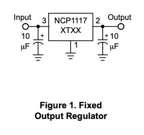
LDO circuit used
Additionally, I wanted to be able to switch my entire system ON/OFF using a slide switch. Anthony said the slide switches we had in stock might be too small to support the current I was drawing (didn't even know that was possible), so a MOSFET would be a good thing to have. I didn't really know how MOSFETs work or how to connect them, and thus began a lesson on how they work as digital switches...
Slide switches have 3 legs. Since I was using the MOSFET as a digital switch, we decided on a p-channel. The MOSFET has three legs - Gate, Drain, and Source. G would connect to the middle leg of the slide switch, D would connect to the rest of the circuit (so, the VCC of the tiny), and S would connect to the actual VCC of the battery (so, not to the tiny).
With most of the detailed fleshed out, I started Eagle-ing. Here are the final board and schematic:
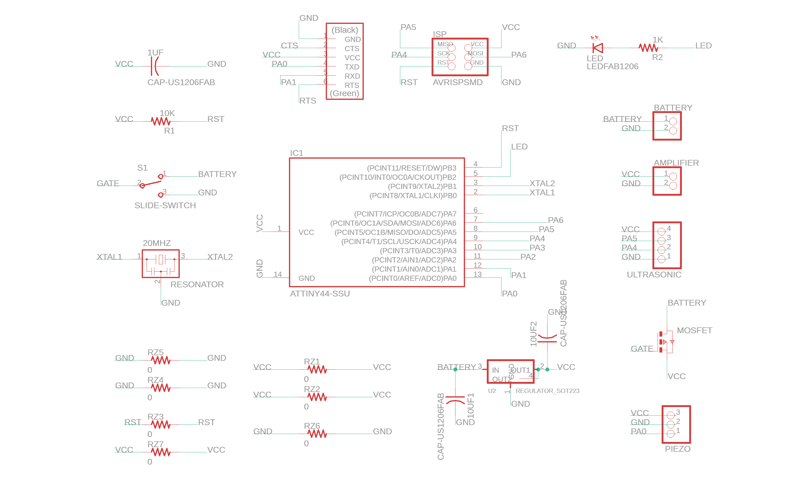
main board schematic
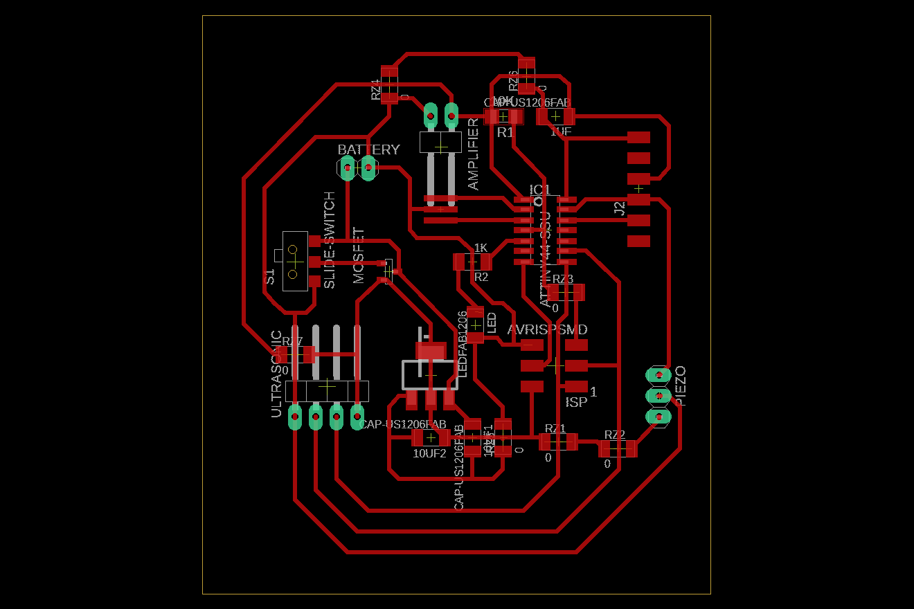
main board file
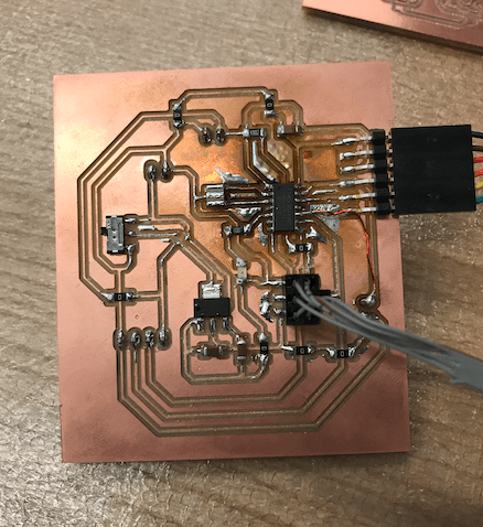
I used the Other Mill, which I rave about in week nine and explain its operation. The traces came out super clean, and after collecting all the components I needed, I was ready to solder!
videos: milling main board on the Other Mill
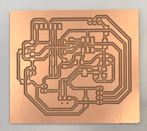
milled main board
I've gotten into a habit of collecting and laying out all the parts I need before soldering. Organizing before sitting down to solder -> would highly reccommend.
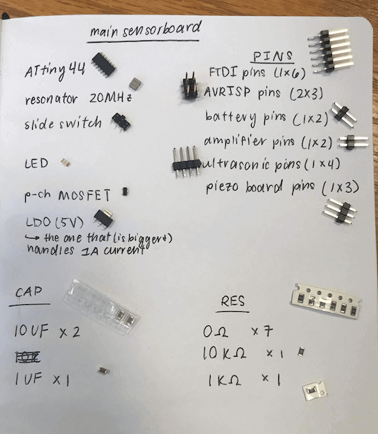
parts used in main board
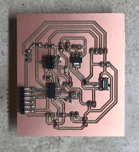
finished main sensor board
a disastrous day
The Saturday before the final project showcase, I was feeling pretty confident that I would have plenty of time to finish and focus on aesthetics. Up until this point, all of my electronics were working well, but I had only been powering through the FTDI cable. I decided to finally try out powering my system with a 9V battery. While plugging everything in excitedly, I misread my Eagle board drawing and plugged in the battery's VCC and GND directly into the pins meant for the amplifier board. This flashed my LED, but I didn't realize my mistake at the time. After realizing my mistake, Anthony told me that while nothing burned (good), I should still check that I could still program my board in case somethign weird happened with the microcontroller.
Lo and behold, when I tried to program my board, it did not work.
So, it was off to resoldering the tiny, but this was quite the process. Listing reasons I had to resolder this component about four times because it's a good reminder of the pains of soldering and to be more careful when plugging batteries in:
1) I burned the board -> note to self to hold the heat gun further away and work faster when using it.
burnt board
2) One of the tiny's pad traces fell off (thankfully it was one of the ones only connected to a sensor pin and not anything else), so there was nothing for one of the legs to solder to. This actually caused me a myriad of problems afterward.
-
It was around try number 2 that I started milling a new board just in case I wasn't able to salvage my original one. I'm putting a picture here because for some reason, this board saw a LOT of burring despite me using the same settings and new (looking) bits.
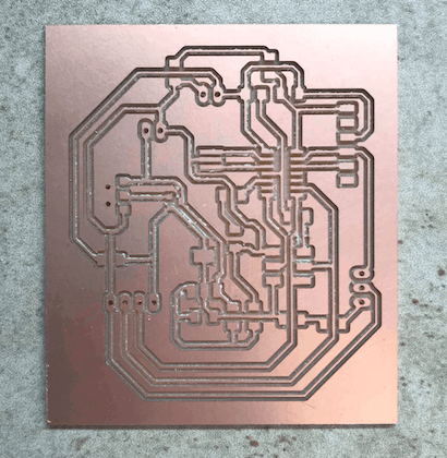
hella burring on 2nd milled main board
3) That exact leg fell off when I was trying to solder it to the piezo pin (too much pulling on it while adjusting the wire) -> new ATtiny44 here I go...
4) I was in a haze and soldered the new tiny chip upside down (pin 1 was in the incorrect position).
I finally got the soldering right and wow! It still didn't work program. I checked all the usual culprits - checking for shorts from VCC and GND (as well as pin connections) using a multimeter, ensuring FTDI connection via typing "lsusb" in Terminal, etc.
When Anthony helped me debug, he found a cold joint, which you'll be surprised to hear I had no idea existed before that very moment. So, what are cold joints?
Cold joints are basically when there's a layer of air between the solder and the headers, which makes debugging really difficult because when you push down on them with the multimeter, you read a connection like nothing is wrong, but the moment you lift up, it's not continuous again. Anthony was able to isolate the cold joint somehow (I really wish I remembered how he did this), and once again, it was back to the soldering station.
Finally! The board programmed. But, it still didn't seem to work completely like it did before - the Serial monitor kept printing strings of '?' when it should've been printing the ultrasonic reading. The baud rate in Serial was correct, and I was using the 8MHz internal Clock that I had been using all semester. Thinking back to past issues, I remembered that clicking "burn bootloader" usually did the trick. Spoiler alert: it did the trick.
videos: salvaged board!
In one of the previous weeks, I mentioned this "burn bootloader" fix but never actually understood how it worked. Anthony explained this a lot better, so I'm just going to put his words here:
Burning the bootloader in Arduino does 1 or 2 important things for us (depending on the type of board):
First, it programs all of the fuses on the chip. When programming through the terminal, we separately ran the commands to upload the code and to set the fuses. The code is rather self explanatory but the fuses can configure a whole bunch of features of the chip and they need to be set properly in order for everything to work as expected. The tiny's chip the internal 8Mhz oscillator BUT also have the internal divide by 8 bit selected. This means that while the clock is running at 8Mhz the chip only sees the change every 8 cycles, so it is really running on a 1Mhz clock. While uploading the code we were (incorrectly) assuming the chip was running at the full 8Mhz. This means that while your chip was attempting to talk at 9600 baud it was really running at 9600/8=1200 baud. Burning the bootloader ensured that the fuses were set appropriately and forced us to run at the proper clock speed.
On chips more advanced than the Tiny series the bootloader also serves a second purpose. The bootloader itself is a small piece of code that sits in a special part of the chips memory and runs before anything else on the chip does. In many cases this is the piece of code that is used to do things like tell the chip how to be programmed over different pins such as the TX and RX pins thereby eliminating the need for an external programmer.
And a link on this topic for future reference
Woooo thanks, Anthony! You're the G.O.A.T.
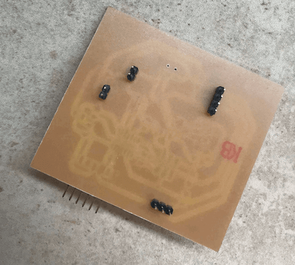
On a more serious note, I marked the back of my board shortly after this debacle so I would never plug the battery in incorrectly again.
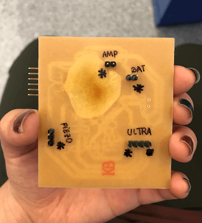
marking the pins of main board
And that's all for the ordeal that was 12/14/19. Board = salvaged. Morale = was lower than it was Saturday morning. BUT, we move on.
speaker system design
Refer to week nine for more detailed explanation on making the actual speaker electronics system.
speaker enclosure design
There's actually quite an art to speaker enclosure design, which I didn't know previously. Basically, there are two kinds of speaker enclosures - sealed and ported. There are some key differences between the two which this site explains pretty well.
According to the site linked above, ported enclosures can dramatically decrease power requirements because they increase the bass output of a speaker by around 3dB compared to a sealed enclosure. To match a 3dB output boost through amplification, the power applied to the speaker needs to be doubled. tl;dr if a ported speaker was powered with a 150W amplifier, a sealed speaker would require a 300W amplifier to produce the same output.
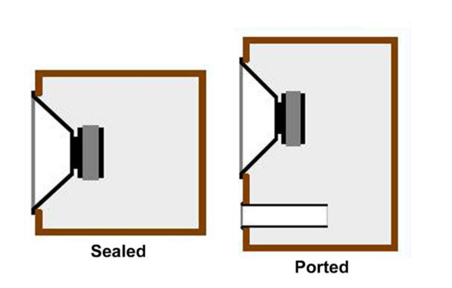
sealed and ported speaker enclosures
During this research phase, I also found this helpful website on how to design a microspeaker enclosure - exactly what I was trying to do! I based my ultimate speaker design on these following principles:
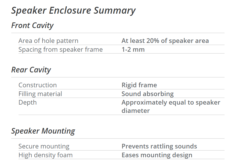
microspeaker enclosure design principles
I'm using the Mallory Sonalert Products Inc. PSR-23F08S-JQ speakers. In order to create speaker enclosures, I needed to look at the part dimensions on the data sheet.
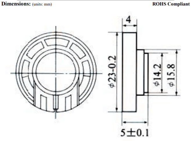
speaker dimensions
So, with my speaker dimensions, the smallest gap between the front panel and my speaker should be 1-2mm, the rear cavity depth should be about equal to the speaker diameter, so that would be about 23mm. I would need to remove a minimum of 20% of the total speaker area from the front panel material (probably with holes of some sort). And I would need to think of a way to secure the speaker between the front and back panels.
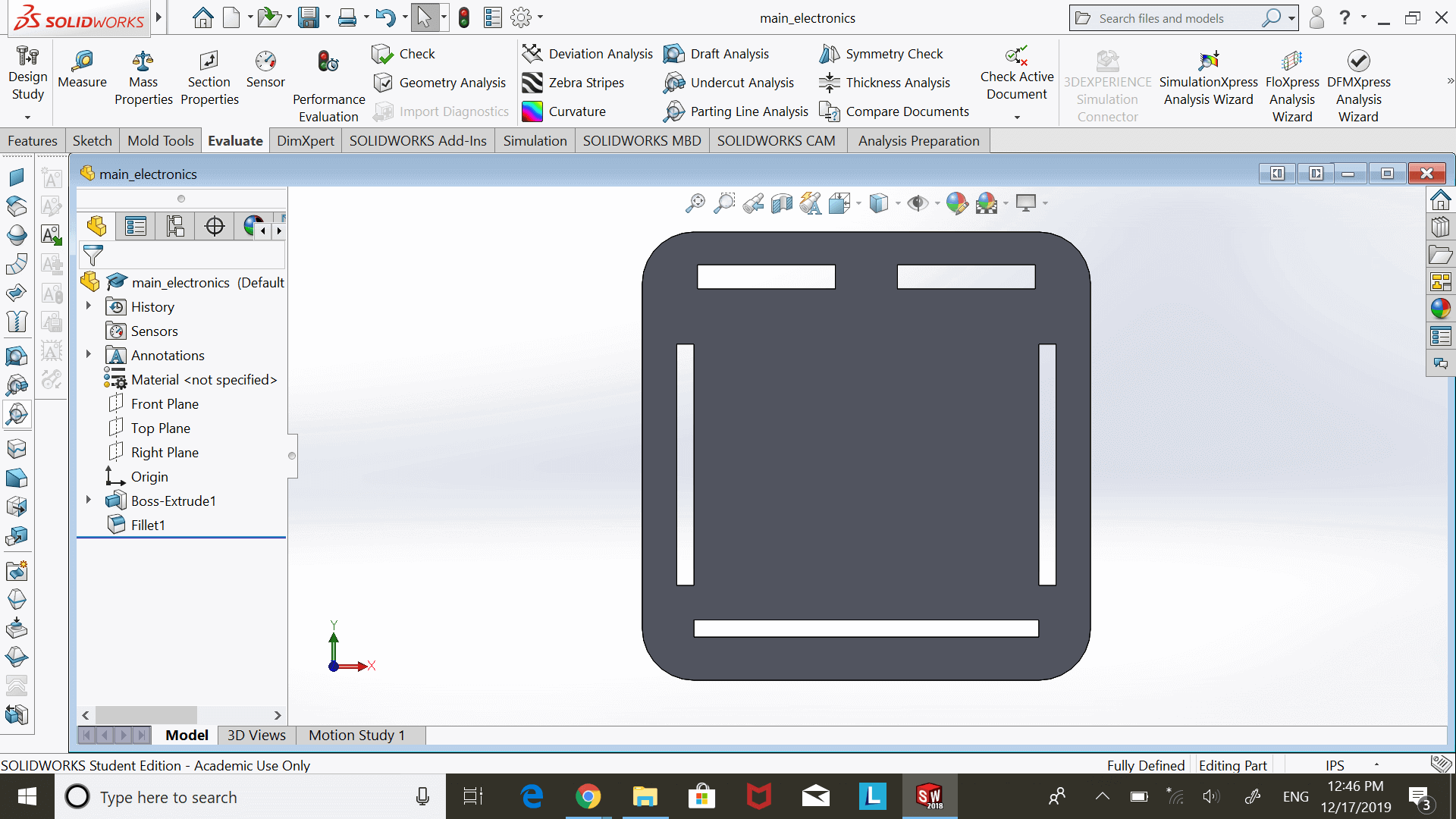
After some sketching, I started modeling the speaker box in Solidworks. Here is the final design:
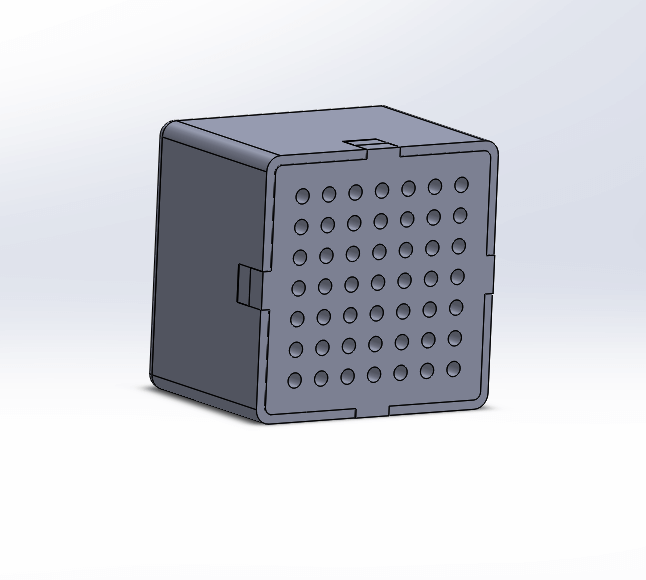
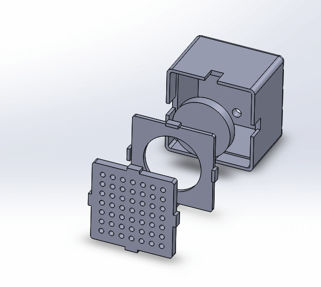
speaker enclosure CAD
I decided that it would be less time consuming to laser cut the front panel of my speaker, so the hole-y part was made by laser cutting 0.125" acrylic. You'll see that there's a hole in the speaker box (back portion), since I anticipated needed a path to wire the speakers to my amplifier board somehow. To secure the speaker, I made a thiner panel with a hole that the speaker could fit and be glued into. Additionally, theres a slight lip in the speaker box where this speaker panel will fit into. There's another lip in which the hole-y acrylic piece would fit on top of it all, creating a flat top to the speaker box but still leaving that 1-2mm gap between the front panel and the speaker itself.
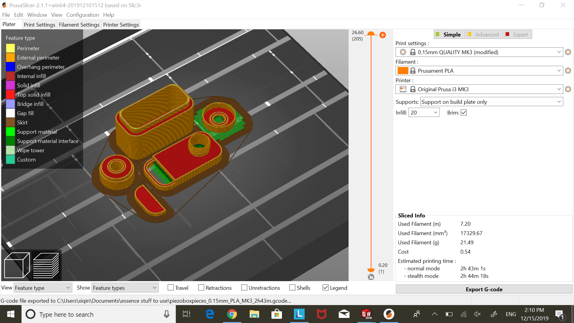
Now that my design was fleshed out, it was ready to be fabricated. I started printing the speaker box on the Prusa and laser cut the front panel.
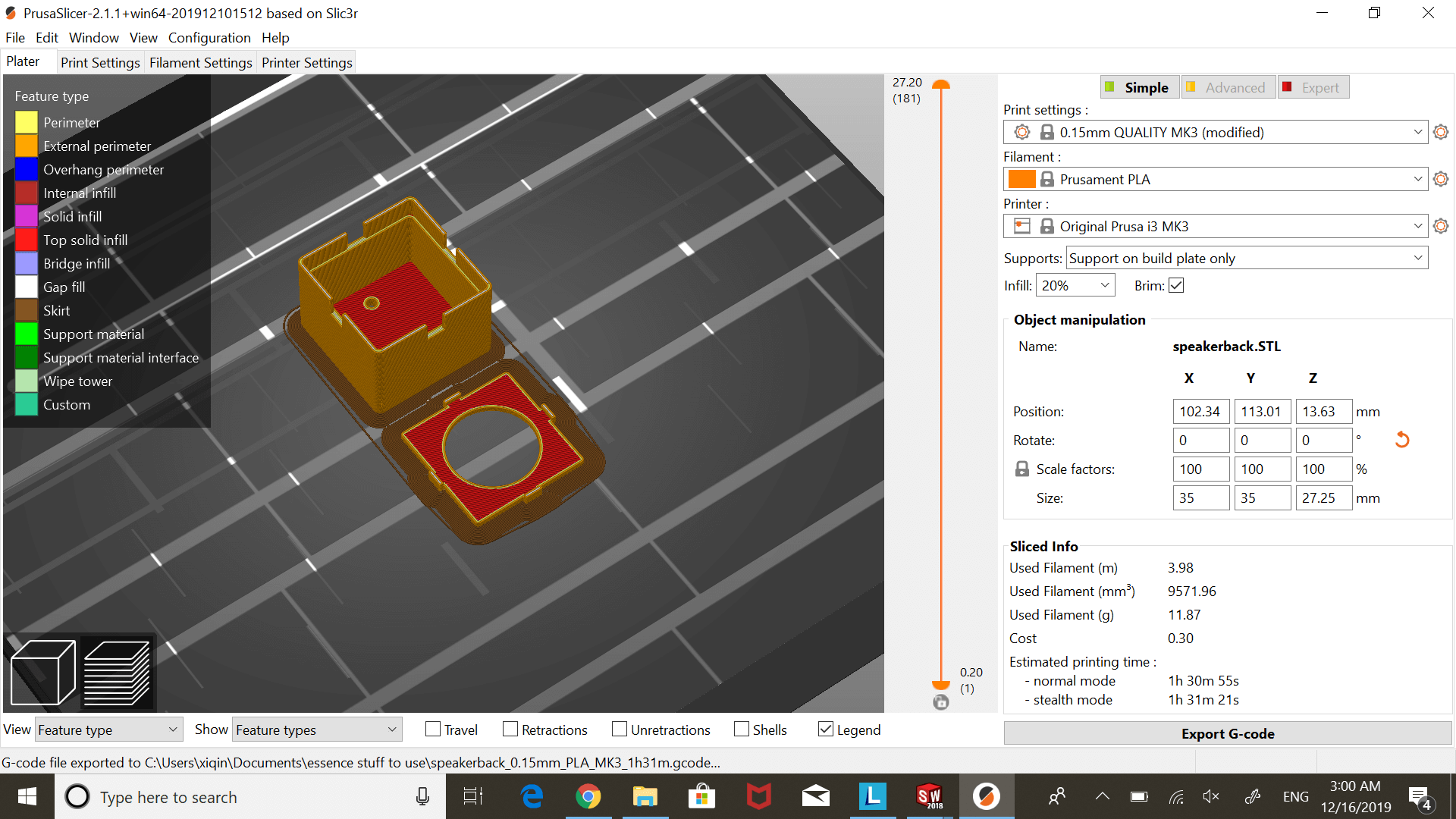
printing speaker box
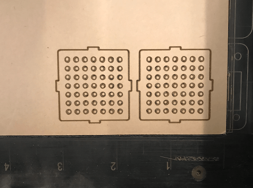
lasercut speaker front panels
ultrasonic sensor and mister system
mistmaker system
I searched up a lot regarding mistmakers that use piezos, so I decided I would give it a try for the aromatherapy component of the spabox. Here's the Instructable that I found useful while designing my own system.
For the mistmaker system, I would need a piezo, a way to make the piezo vibrate, some kind of cotton diffuser stick, and water - all enclosed and packaged nicely to integrate into the spabox.
Doing more research into piezo mistmakers/atomizers, there's actually several available for purchase on Amazon alone. Looking at the specs of this piezo board (that I ended up using), Anthony let me just purchase one because we were unsure if we would be able to reach the 113KHz of the piezo board using the parts we had in EDS.
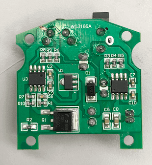
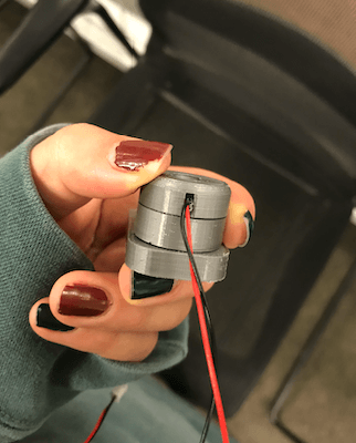
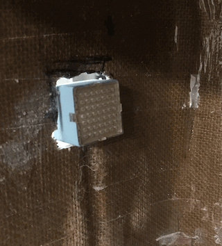
On these piezo board, there's a button (to turn the piezo ON/OFF) and a barrel jack attached (for power). The button is interesting - press it once and the piezo turns on, press it again and the piezo turns off. However, the button itself is similar to a tactile button (not one of the ones where you can feel it latch when its pushed/unpushed). Wanting to control the piezo with the ultrasonic sensor through my main circuitboard, I needed to bypass this button and redirect the VCC and GND connected to the barrel jack.
hacking the piezo board
I first removed the barrel jack and soldered red and black wire for VCC and GND. These would connect to the 5V and GND of my ATtiny44. Easy enough.
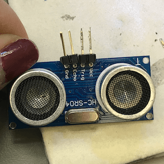
Bypassing the button was a bit more difficult. First, I needed to determine which of the button pins was actually talking to the piezo/responsible for turning it ON/OFF on a button push. Looking at the board traces, Anthony told me that the upper left pin was connected to the microcontroller, while the other three look like they're grounded.
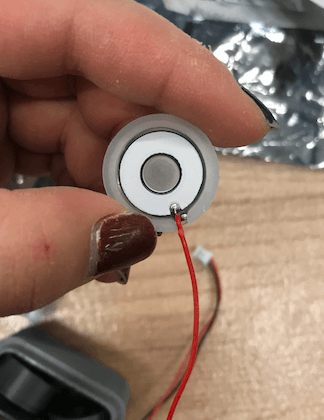
piezo
original piezo board
videos: how the piezo board originally worked
So, I would need to run a wire from that upper left pin to a pin on the ATtiny44. Before doing this, I tested the piezo board on its own (using the still operational button), connected to a power supply. It works great and produces a lot of mist! I was now ready to integrate the piezo board with the ultrasonic sensor.
integrating with the ultrasonic sensor
Refer to week eight for more detailed explanation on connecting and testing the ultrasonic with the main board.
The vision: when the ultrasonic sensor reads a value under 6" (a little bit less than half of the width of the box), the piezo will start misting.
I had already gotten my ultrasonic sensor to read distances pretty reliably, and now I just needed the tiny to tell the piezo to turn on at the correct times. Here's the Arduino code:
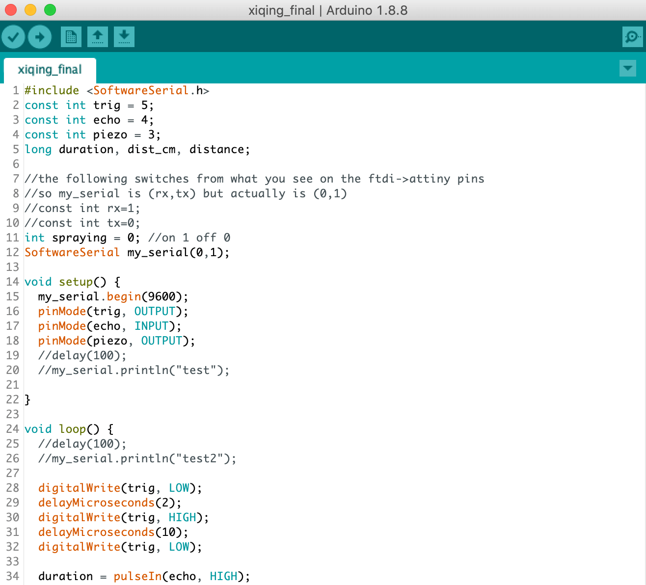
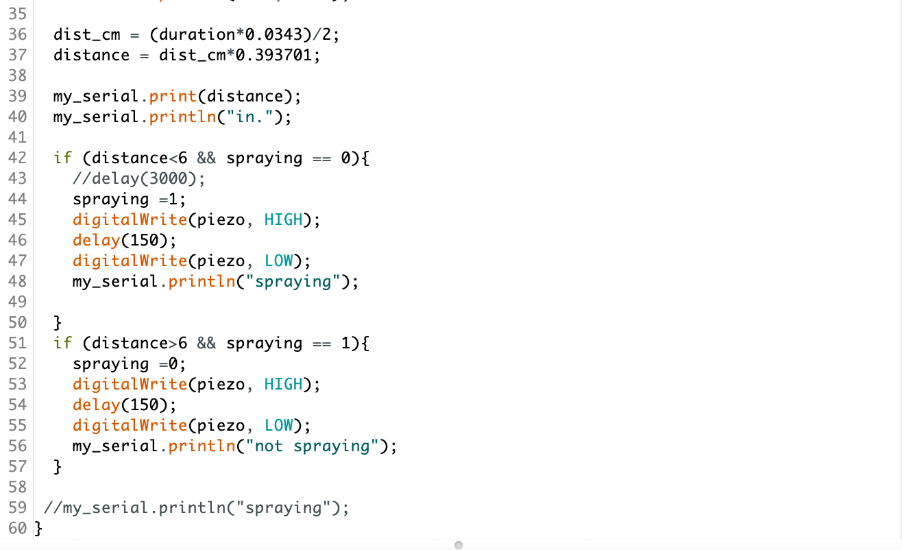
code for spabox
I encountered some issues in testing. The first had to do with my original board connections. I had connected the piezo pin - I'm going to call it the piezo pin, but it's just the "bypass button" pin on the piezo board - to one of the FTDI pins, which was messing a bit with the system. Whenever I put my hand over the ultrasonic, the piezo would turn on and stay on, even if I moved my hand away. The only way to turn the piezo off would be to put my hand over the ultrasonic again, after which the piezo would stay off, even if I moved my hand away.
I fixed this by resoldering this piezo pin to an open pin on the ATtiny (that wasn't one of the FTDI ones). After this, the ultrasonic/piezo system worked pretty well!
videos: the ultrasonic/piezo mistmaker system works!
fully integrating electronics
At this point, I knew that all the separate electronics systems were working independently with my main board. Now, it was time to test the speaker and ultrasonic/mistmaker systems together like they would be in the spabox's ultimate operation.
videos: electronics system works!
Nice! It worked. I was super happy about this. Now, it was time to connect the battery. Sorry this documention is getting more and more melodramatic and I go.
Yet again, I ran into some issues. Checking with a multimeter, the first I noticed was that my board wasn't getting 5V at the VCC of my ATtiny. Following (the actual) first step of debugging - find Anthony (kidding...) - it was determined that my MOSFET was incorrectly connected, though I spent so much time confirming the connections on my main board were correct :,(
There wasn't enough time to make a new main board, so I decided that I would be OK without a switch on my system, especially since the only switches in the EDS are the very tiny, not super easy-to-use slide switches AND I hadn't accounted for their size when making my board initially, so the side of it was pressed against the surface of the board, making it even more difficult to use.
I cut the traces to my switch, confirmed that everything was now getting 5V (we love a good LDO), and moved on!
The second was that using the battery somehow messed with the operation of the speakers alongside the ultrasonic/mistmaker. When the piezo sprayed, the music would cut out, and when it was done misting, the music would continue playing.
I tested the current draw of the piezo board with the power supply, and Anthony said he was surprised at the large amount of current (~0.5A) the piezo board drew.
videos: weird activity when powered by 9V battery
The weird activity was probably attributed to this, but because everything worked OK with a power supply or via a FTDI/laptop, I decided to leave the battery for later and chugged along to finish my project.
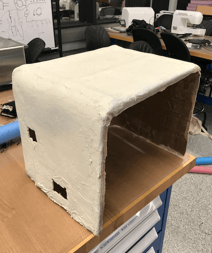
making the spa box
Refer to week thirteen for more detailed explanation on making the composite for this project.
cutting holes
Before trying to use Bondo or spraypaint on the box, I needed to make some holes in the composite's wall in order to fit some of the electronics inside - namely, the piezo mistmaker, speakers, and ultrasonic sensor. The hope was that by making holes so that these parts were nestled within the walls of the box, the overall spabox would look more polished. This, retrospectively, also might've been well-intentioned but misguided, as the EDS doesn't have a specific tool that can cut through composites very well.
Anthony and I thought about using the Dremel grinder, but decided that might be slow and would probably damage the tool heads pretty quickly. Instead of that, we decided to go with a screwdriver and hacksaw.
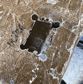
hole in composite (courtesy of drill and hacksaw)
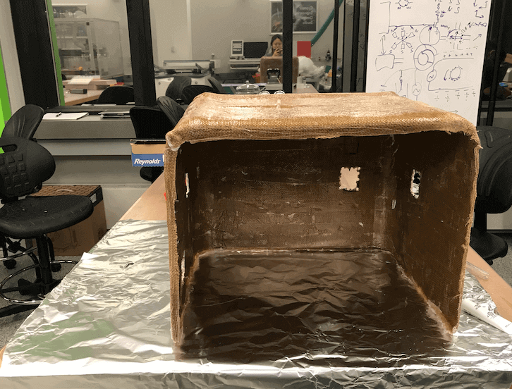
composite box with holes
They weren't the cleanest holes ever made, but they would have to do.
finishing composite
After my composite was ready in its raw form, I wanted to finish it to make it look a bit nicer. I had never used Bondo All-Purpose Putty, but it seemed like a tried and true way to finish a variety of parts (including 3D printed objects)! I decided to buy some and give it a go with my composite box.
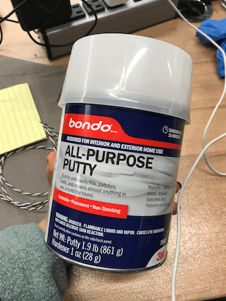
bondo all-purpose putty
I (and the rest of the people in EDS at the time) realized very quickly that Bondo smells absolutely horrible. And the EDS has little ventilation. So, I took this whole finishing operation outside. It was quite cold, but we got it done. Kind of.
Bondo instructions are a bit odd. Basically, there's this putty and a tube of hardener. The ratio is about a golf ball of putty to 1" of hardener paste. You then mix well and keep the mixture as thin as possible to keep it from drying too quickly.
It took me a really long time to do the entire exterior of my composite, and the finish wasn't super smooth. I had never worked with Bondo, and I wasn't ever able to find the nice balance between just squeegee-ing the paste around on the surface of my composite to leaving glops of it in various places. Additionally, it was pretty difficult trying to spread it before the Bondo would start to dry up on me while trying to work it around.
Something I realized a bit late was that being outside, the Bondo was drying/curing a lot slower than it should've been. The packaging recommends that you leave Bondo to dry at about 70 degrees F (where it should only take about 20 min.). However, it was SUPER cold outside. This probably made my drying time much longer than it should've been.
finishing composite and 3d printed cases with bondo
I did bring the box inside at some point to speed up the drying process. That smell is so incredibly pungent. The box had probably been sitting outside for about and hour, but it still smelled very much like Bondo in the lobby of the building once I brought the box indoors.
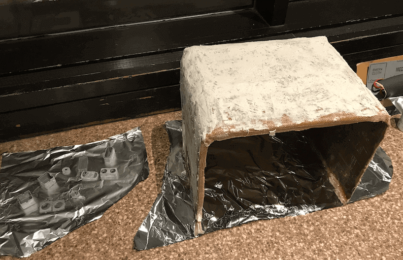
Finally, the Bondo felt dry enough to start sanding. It probably could've used a slightly longer drying time, but I was running out of time for the night, so I just went for it.
Using the coarsest sandpaper the EDS has, I worked up a sweat sanding the composite. Some parts ended up decently smooth, but after I decided I had done enough sanding for the night, there were still quite a few visible patches of Bondo that hadn't yet been sanded flush with the rest of the surface. The end result looks a bit like wall spackle, but that would have to do.
I bought a nice bone colored spray paint and took the composite back outside to spray paint. This made it look a little bit nicer - I think?
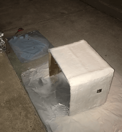
spraypainting
All in all, I don't think I would've used Bondo if I had known how it was going to turn out. The natural composite look and feel wasn't pleasing, but I actually think it might've been a smoother surface to paint on than the spackled Bondo surface. That being said, I'm sure with better Bondo usage, the correct environment (i.e. a lab with a fume hood) and an electric sander, the composite would've turned out much more aesthetically pleasing. However, I did learn a lot about some useful finishing techniques throughout this process, which is something I'll take note of for the future.
finished composite box
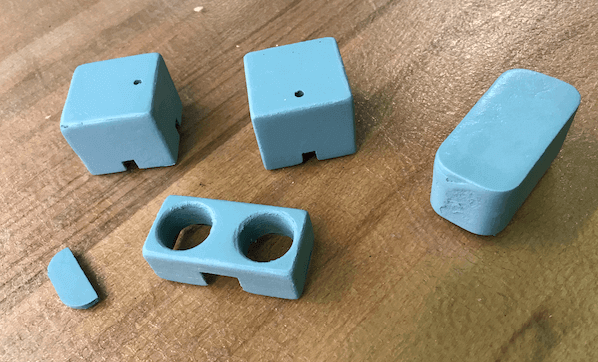
electronics cases
My electronics system had been working reliably, so I started CAD for different ways to enclose the speaker system, piezo mistmaker, and ultrasonic sensor so my project looked a little more finished.
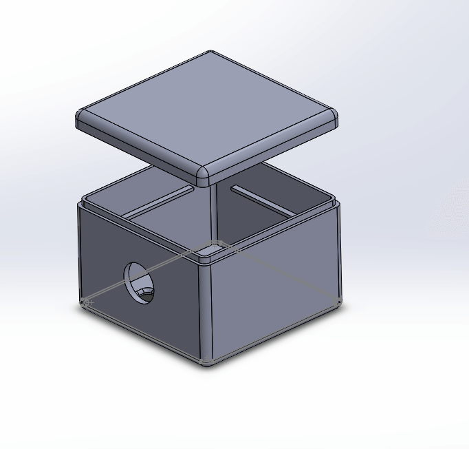
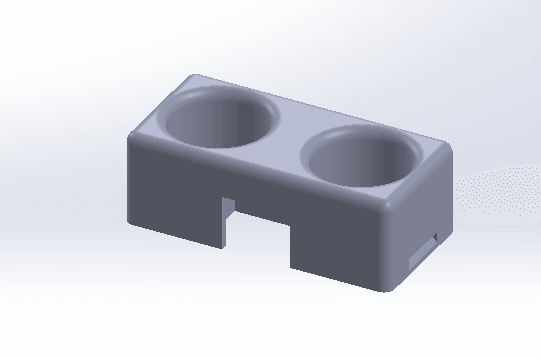
piezo mistmaker enclosure
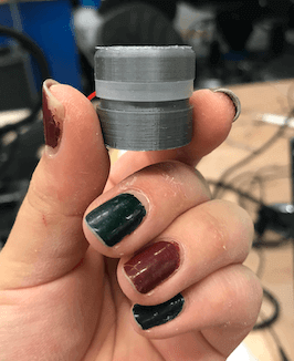
I started with the piezo mistmaker enclosure. It features a lower container to hold water, a cap with a hole that a cotton diffuser stick can fit through, and a lid that can go over the piezo that would lay on top of the cap and the top of the diffuser stick.
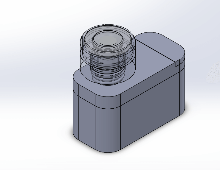
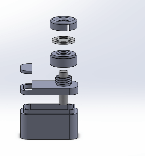
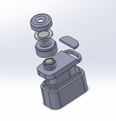
piezo mistmaker case CAD
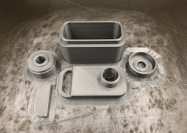
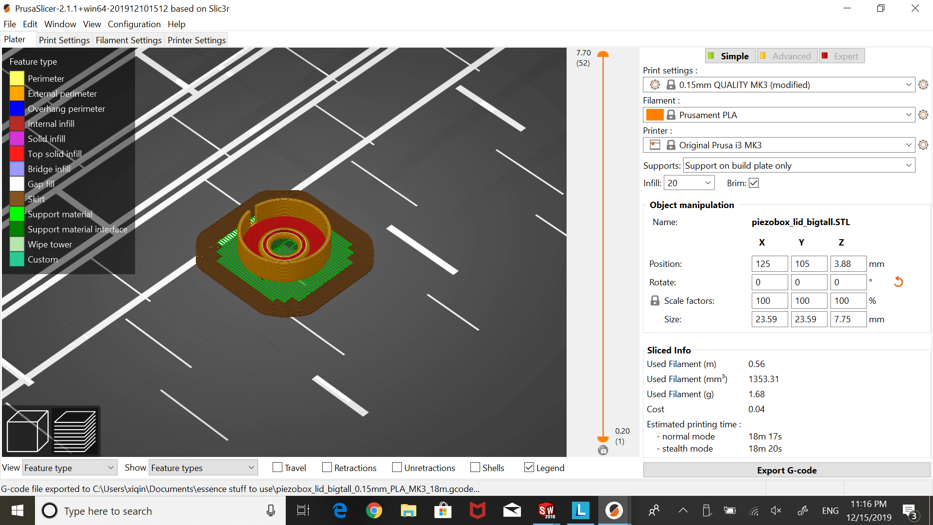
3D printing piezo mistmaker case
The first lid/cap didn't fit very well, so I experimented a bit with the CAD design and reprinted. Good thing the Prusa is fast!
first caps don't fit :(
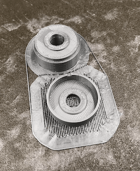
reprinting caps
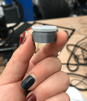
After experimenting a bit with the depth of the hole in the lid, I finally got to one that was still secure but allowed the piezo's wires to travel through without pinching them.
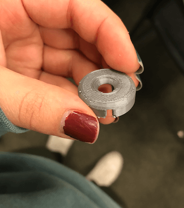
final piezo cap
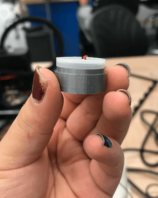
it finally fits!
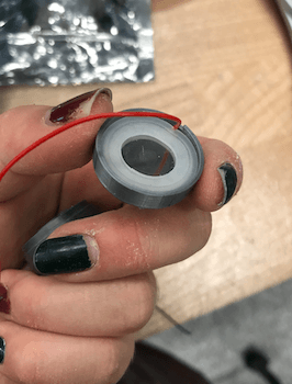
Now for the moment of truth. Would the piezo mistmaker still work with this case enclosing it? I tried it in a couple different orientations, but I was disappointed with the amount of mist it was producing compared to that of just putting the piezo directly into water.
I had purchased these cotton diffuser sticksoff of Amazon for this project, but I think they were possibly a little too dense/not porous enough for water to easily travel through. The piezo made mist faster than water could travel to the top of the diffuser stick.
I thought cutting from the thickness of the stick might help, so I tried it out. It actually worked! Granted, it still didn't produce the impressive amount of mist that I saw by placing the piezo directly on the surface of the water, but it was definitely an improvement.
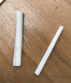
cotton diffuser sticks
videos: experimenting with diffuser sticks
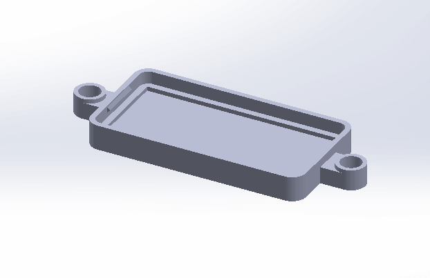
case for the amplifier board
CAD + ideation
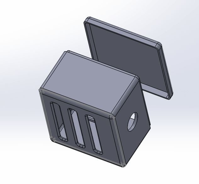
amplifier case CAD
case for amplifier board
case for ultrasonic sensor
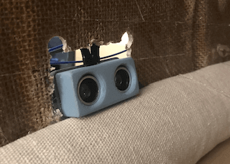
I ran out of time with the ultrasonic sensor case, but thankfully, there's a couple STLs available online. The ultrasonic sensor I'm using is the SunFounder Ultrasonic Module HC-SR04 Distance Sensor (which you can buy here), and I actually found a already modeled enclosure for this exact part (click here for the STL), so I just downloaded and printed it on the Prusa.
ultrasonic sensor case CAD
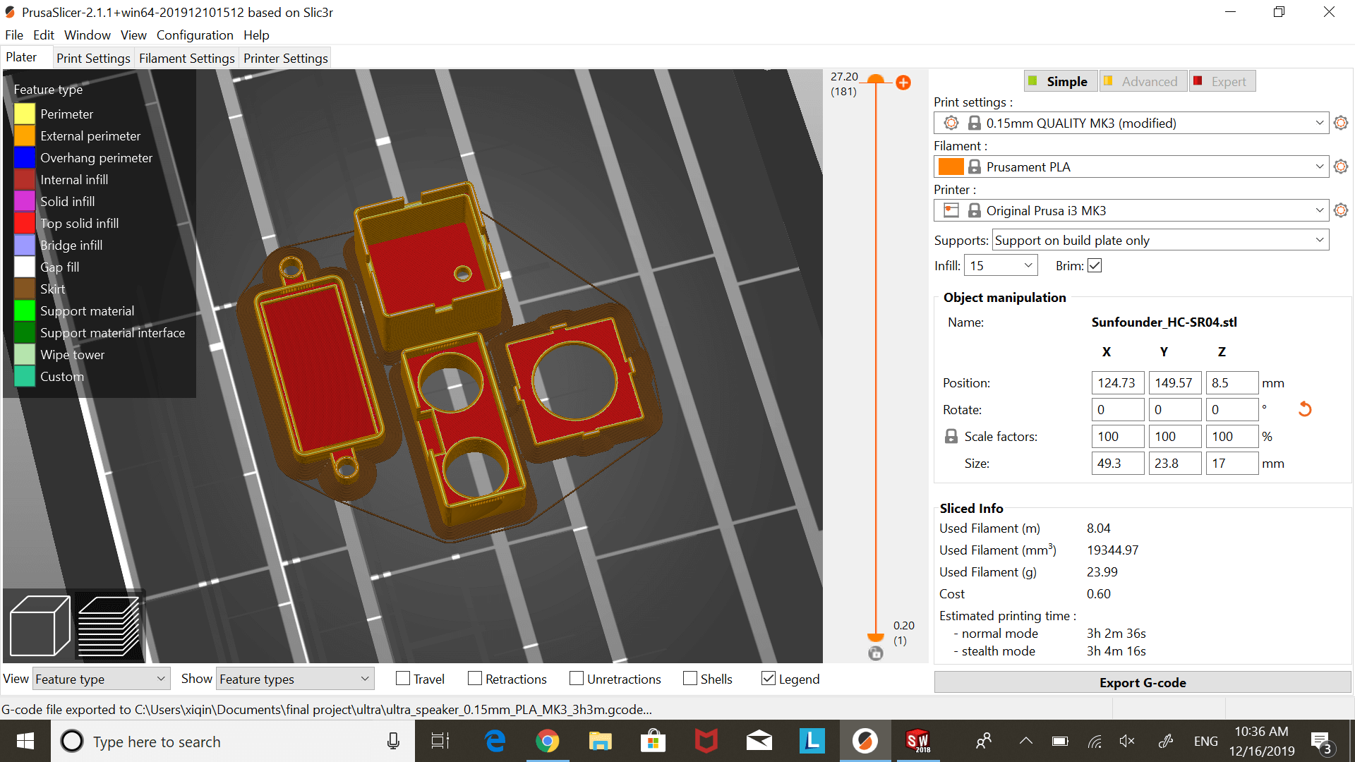
3D printing ultrasonic case (and another speaker box)
The only thing is, while the case fit the ultrasonic sensor, the opening that the sensor pins are supposed to stick out of the case is on the wrong side of the board. The way that the case is designed, the pins would need to come out of the same side of the board as the two cylindrycal sensor heads. I thought it would take much longer to change the STL and print it again, so I took the easier route and resoldered the pins on my sensor to the other side of the board to fit inside the enclosure.
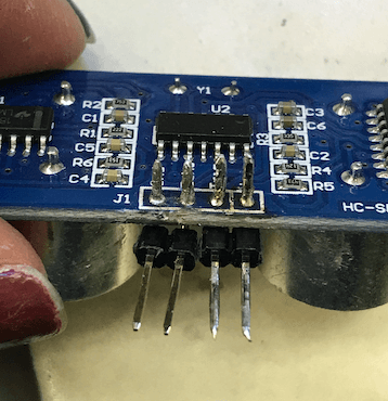
resoldered ultrasonic pins
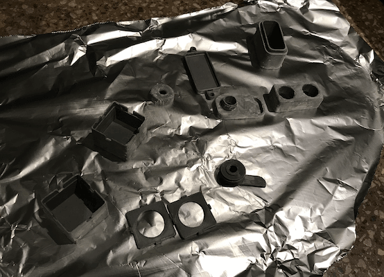
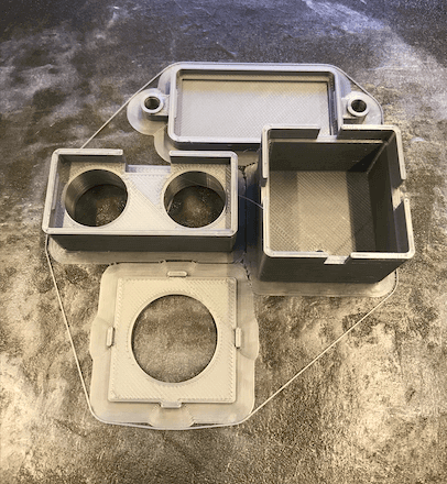
Since I had a lot of Bondo, I decided to finish the 3D printed parts as well. So, while I was outside working on the composite box, I also took the 3D printed cases outside and smoothed some Bondo on all of them as well. When these pieces were dry, I sanded them alonside the spabox, and took them outside again to spray paint spa blue (pretty fitting, right?)
finished cases
The finished 3D printed actually ended up looking really nice and polished, so I was so much more pleased with these than the composite box.
having a gr8 time! circa spraypainting outside in freezing temperatures around midnight
spabox finishing touches
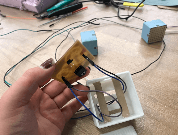
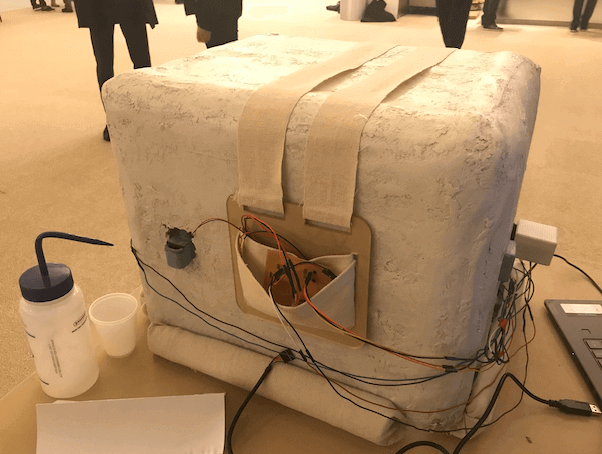
Once everything was coming together, I realized that I had forgotten to CAD a box for the main circuitboard and battery to rest. There wasn't much time to CAD and 3D print something at this point, so I decided to make a quick pouch so I at least had somewhere to put the main board, battery, and piezo board.
laser cut pouch back
I lasercut a panel with some slits in it where slid fabric through to hot glue to the back of the acrylic panel, making a pouch on the front of it. Though not super protective or neat, this fabric pouch did it's job of keeping the the homeless electronics a bit more contained.
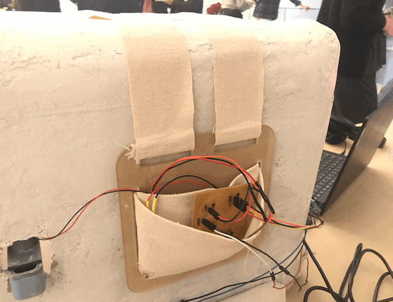
electronics pouch
The edges of the composite were pretty rough (and the epoxy/plastic shards gave me many cuts on my hands and arms). The EDS only had this clear silicone tubing, which I tried to cut and wrap around the edges of the composite - taco style - but the tubing diameter just wasn't large enough. It was at this point where I thought, "If only I had pool noodles!"
It was a bit of a joke at first, but the more I looked at the dimensions of my box, the more desperate I became for pool noodles. Thankfully, one of my friends lives in a dorm where they happen to have several pool noodles (that they use for play sparring, not swimming), and I was able to obtain pool noodles to cut up and wrap around the rough edges of my composite. And, since the pool noodles didn't really fit the spa color scheme, I used some of the excess fabric from the main electronics pouch DIY to wrap the pool noodles.
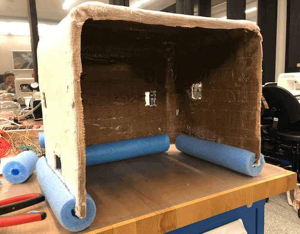
pool noodle cushions
I'm actually quite pleased with the way that the pool noodles add cushion and height to the spabox, as well as protection for the box and the person using the box alike :)
The next step was to place all of the electronics in the general area where I would ultimately glue them down and cut and solder wires where there were still header wires. This took a bit, but eventually I got rid of most of the header wires and replaced them with longer, neater wiring.
Finally, I was ready to secure the electronics into place. I chose to hot glue the speakers, ultrasonic sensor and case, and piezo mistmaker and case into the holes I made in the composite walls. With the amplifier board, because I never made a hole for it to go into, I just used a piece of velcro to secure it to the right side of the spabox, close enough to the edge (and the user) so that users can look at their phones to adjust music/volume/alarms/etc. while they're laying inside of the box.
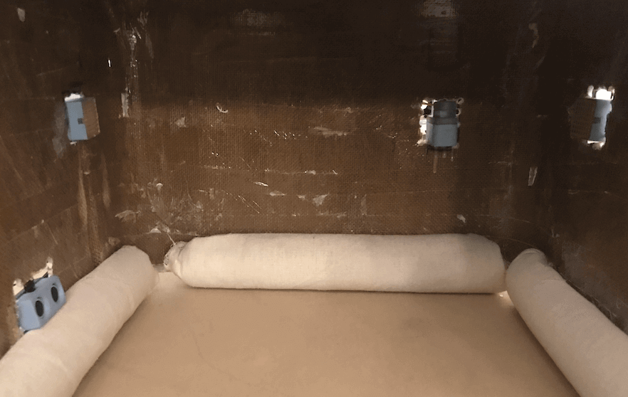
electronics cases hot glued into holes in composite box
videos: first time testing spabox in lab
12/17/19 final project showcase
videos: final showcase (with human subjects)
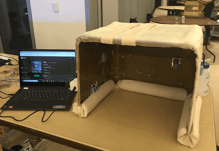
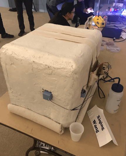
the spabox
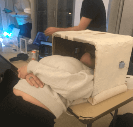
people trying the spabox out
spabox fabrication process in summary
videos: spabox process video
And we're out!