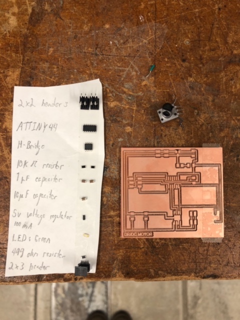
This week presents a challenge in the form of output devices, which is both productive and intimidating as it relates to the final project. The specific goals for this week include fabricating a new board and incorporating both a DC motor and potentiometer.
I started the week by referencing both my earlier Hello World board design from the Electronics Design week, along with Neil's DC Motor Hello World Board.
After speaking with Brian about the specific functionalities within the DC Motor board, it helped to clue me in on what should be added and what should be modified. Brian suggested first and foremost to add a resistor and LED in order to provide an initial sanity check. So long as these were routed correctly, the presence of a bright LED light would tell me that I've soldered everything together and hadn't shorted anything.
Additionally, I needed to add my potentiometer. This seemed most appropriate in the top right corner, as this was out of the way and had access to both 5V, Ground, and an available finger on the ATTINY44 microcontroller.
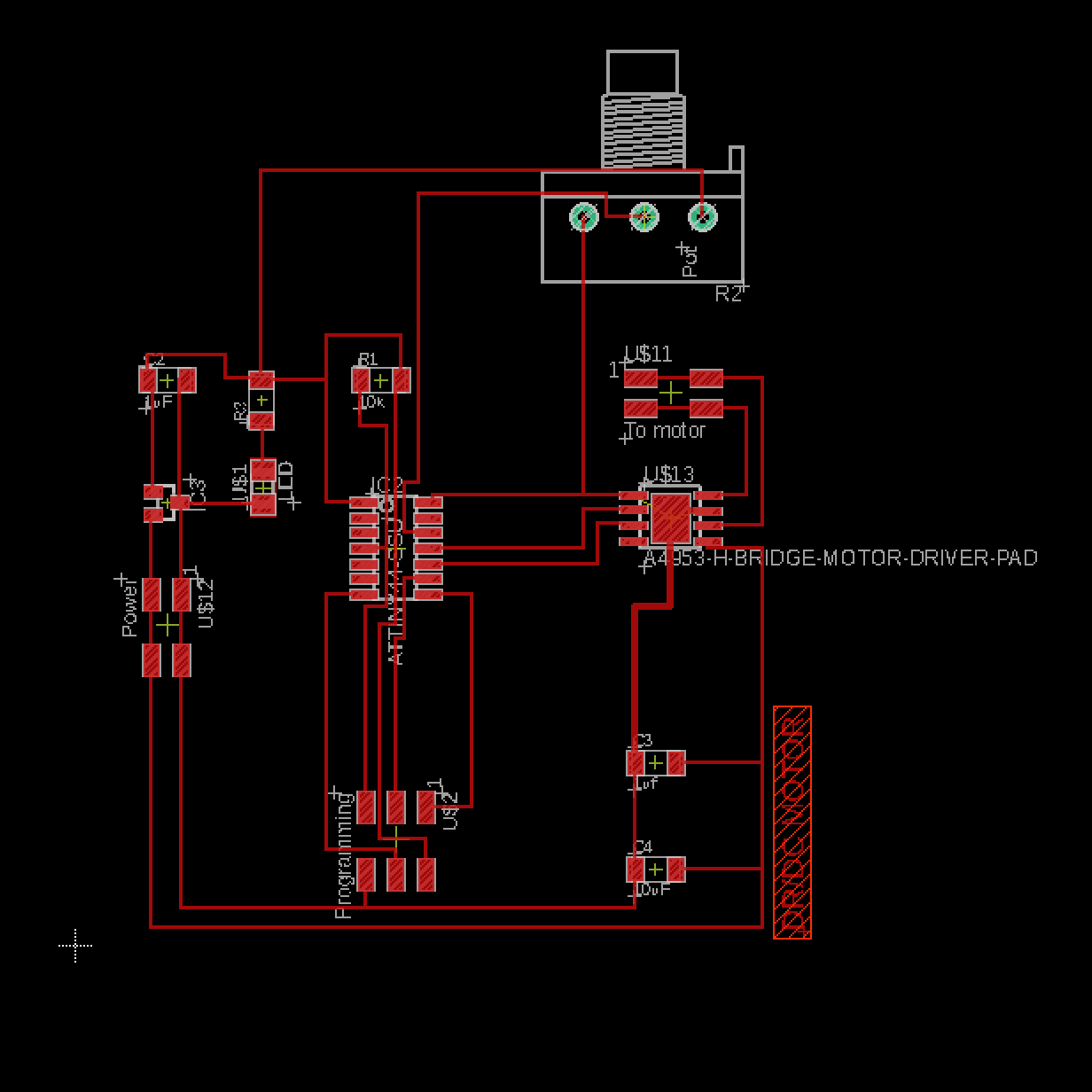
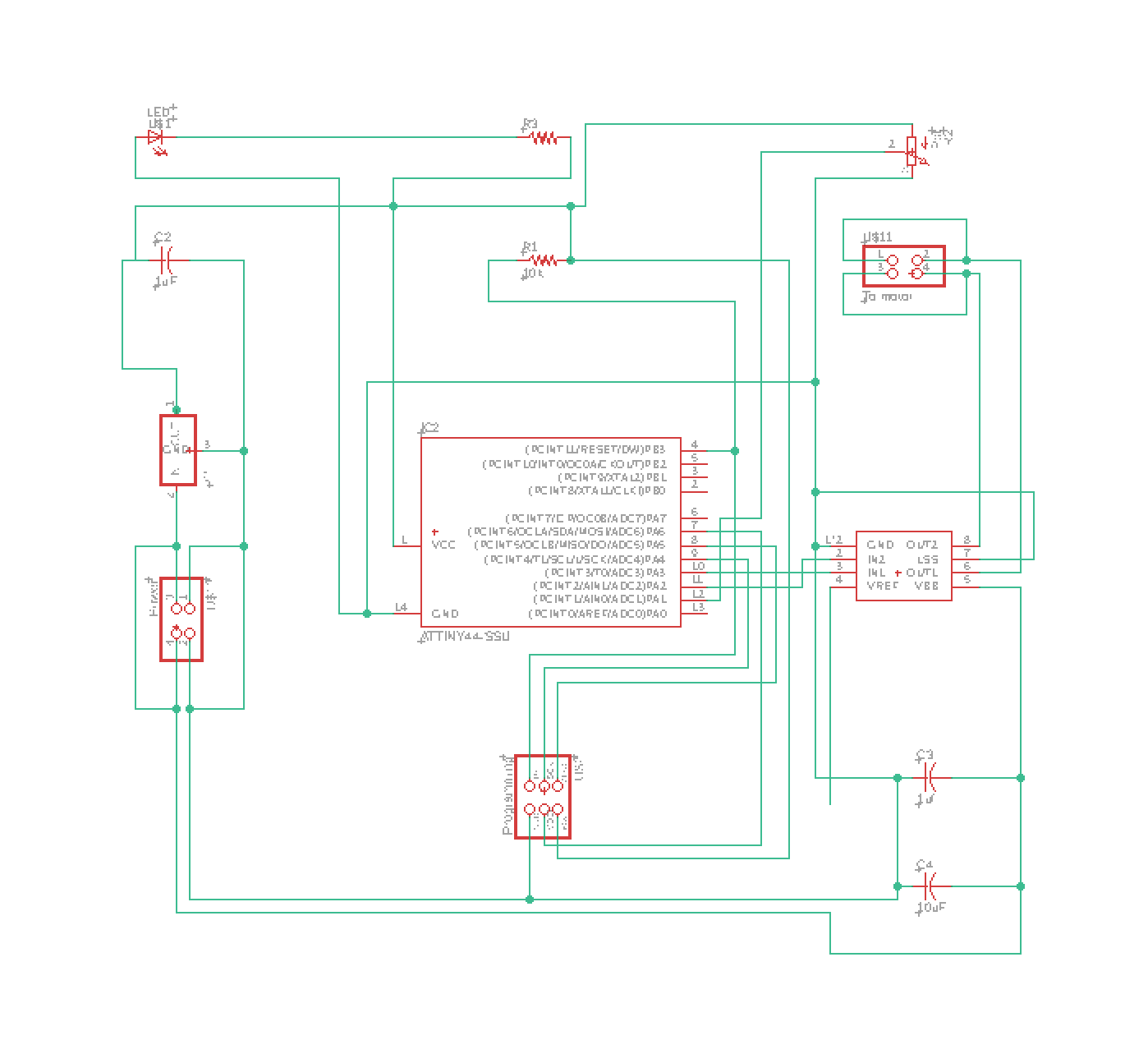
Getting back up and running in Eagle was not fun or quick, as I struggled to find the original library from our course, became lost in the otherwise extensive part library, and botched together pages from HTMAA in order to understand what each component was called. Furthermore, remembering the adjustments needed within the program and thicknesses proved to be more challenging and time consuming than I remembered.
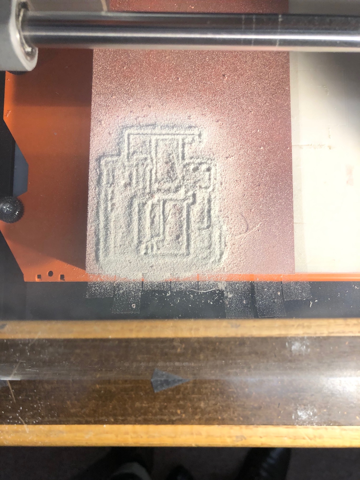
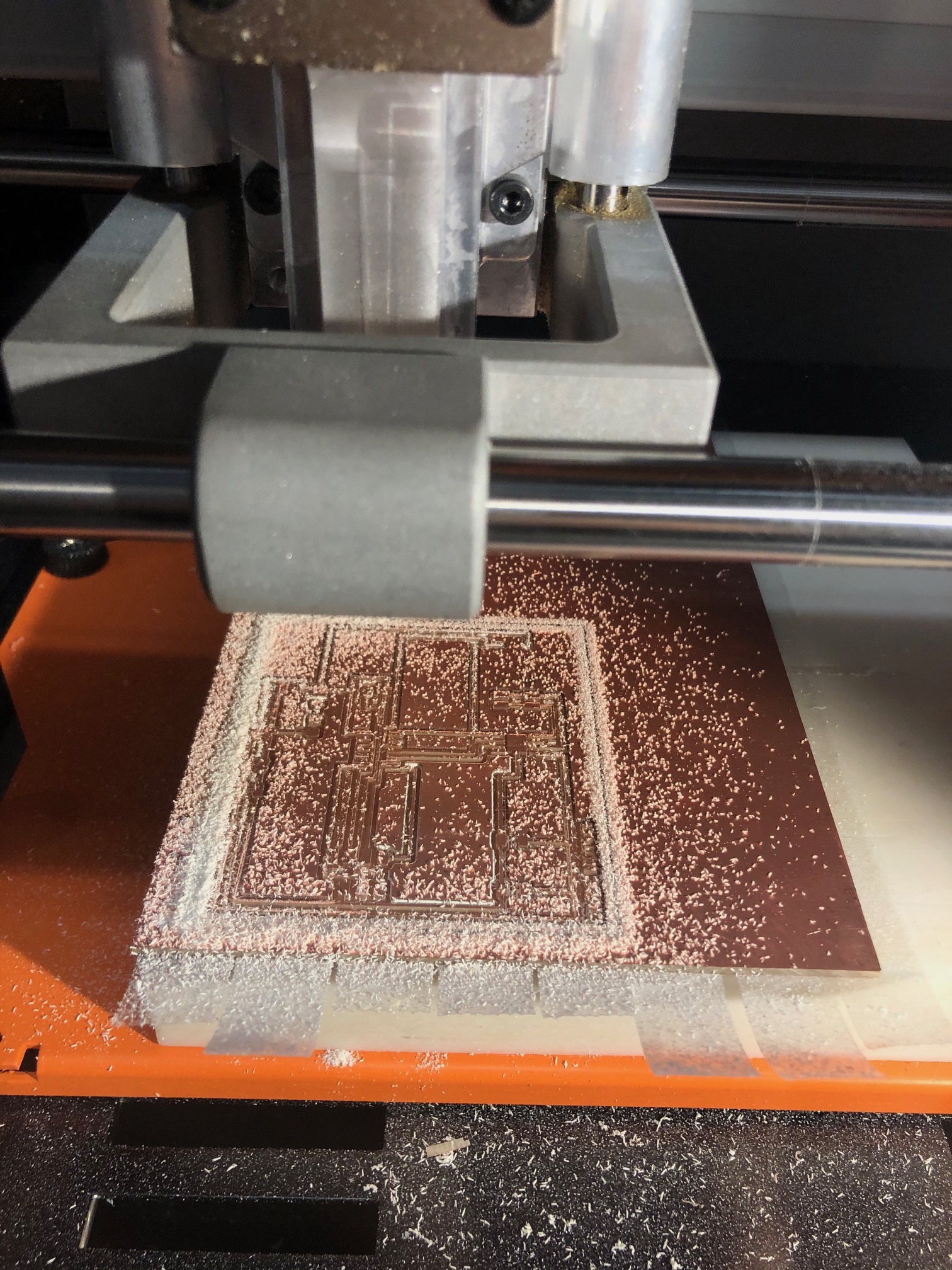
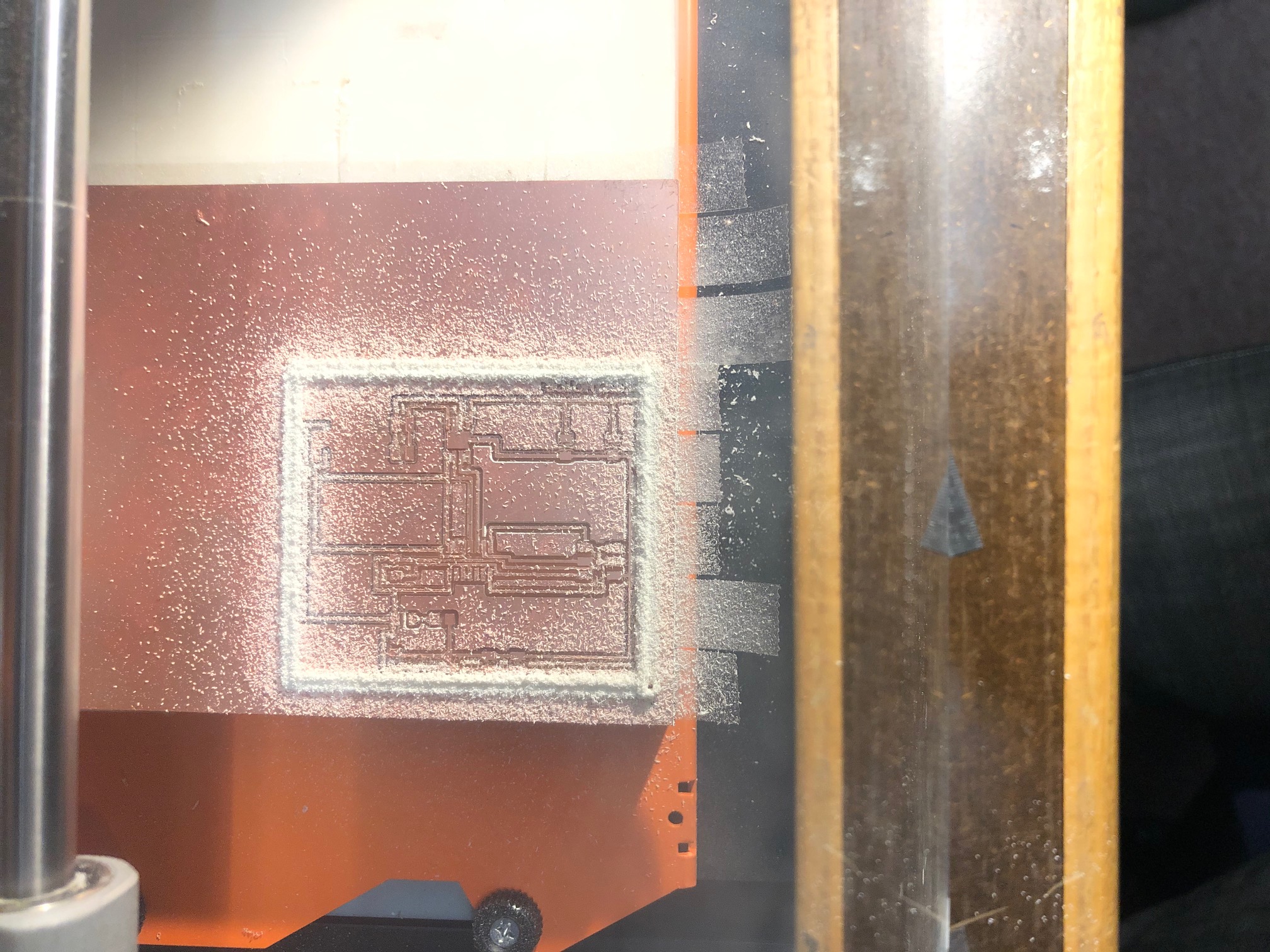
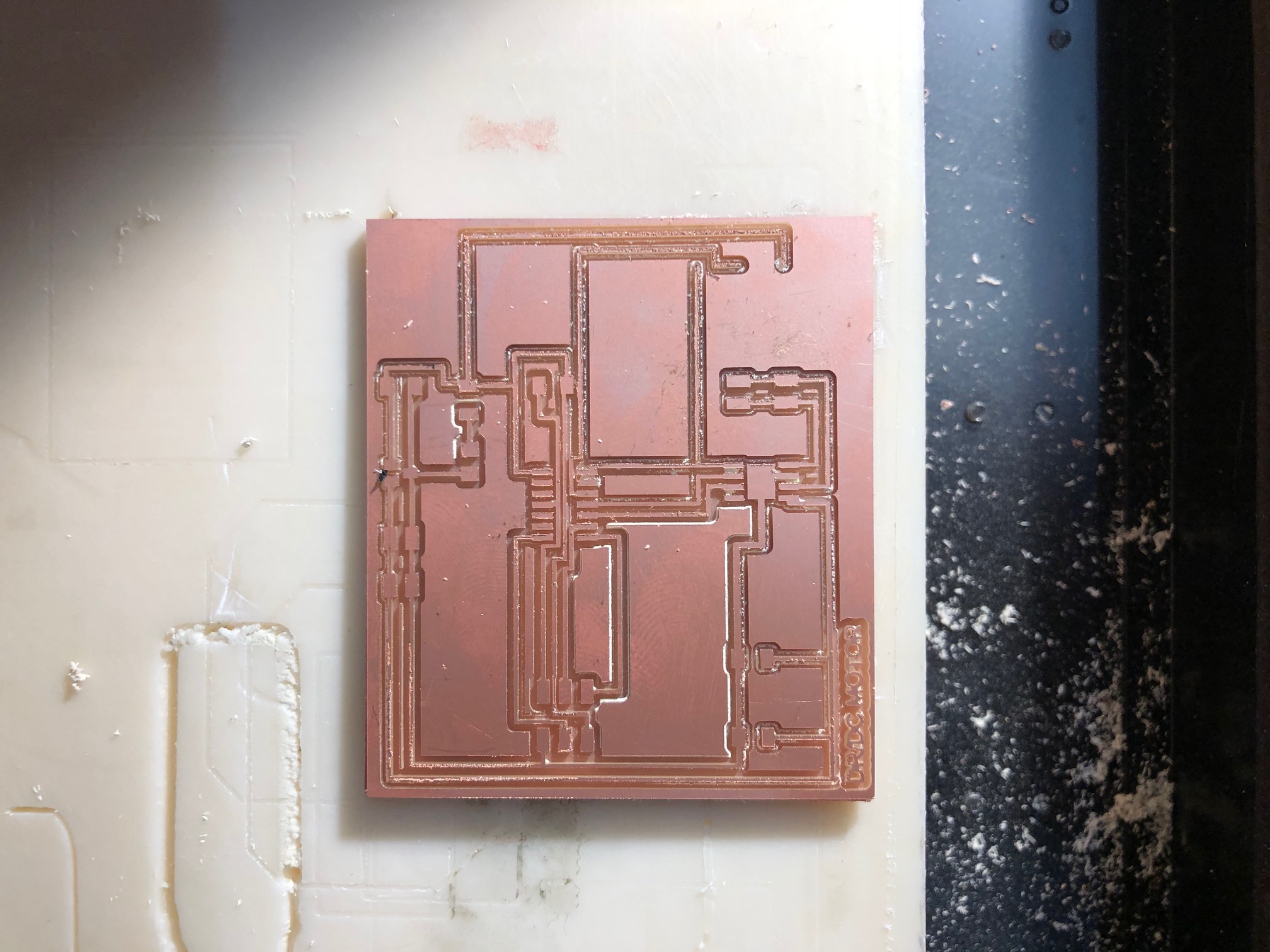
Upon getting back to milling, I setup my file and again adjusted the resolution. The resolution needed to be doubled because I was working with Eagle on MacOS. I went back to Mods for milling and set up my file for traces. The first cut was set at a depth of .006 inches, which barely touched anything. I thought I had recalled the setting as .045 inches of depth and therefore restarted the file. This did not damage the end mill, but did lift the copper substrate. I then stopped the file and went back to the drawing board. Thinking that I was going to play it safe, I ran the file with a .008 cut depth, but with four passes. This would cut down to .8 mm or 32 mil, which did not seem so bad. It took forever! Nonetheless, after waiting for what seemed like forever, the board finally finished and was not destroyed. The cuts were somewhat deep, but came out quite nicely. I then swapped end mills to cut the outline, but again depended on the presets from before. This did not cut through. I removed the copper substrate and proceeded to worry. Given that the substrate was fairly long and located semi-precisely along the y axis edge of the mill, I remounted the substrate and recut the outline. While not an ideal situation, it did indeed work nicely and did not interfere with existing traces.
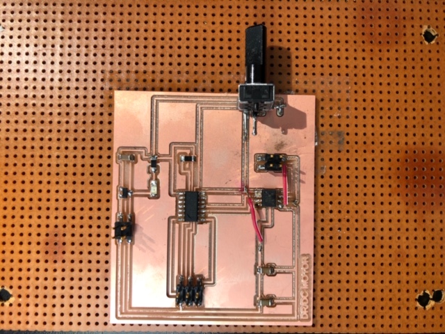
After soldering on the necessary components, I ran into a couple of issues. In one instance near the H Bridge, I neglected to connect a pin to ground. In another instance, I had very thin traces and somehow managed to remove some of the copper layer before completing the board. The potentiometer was also quite unstable due to its bulk and less than (structurally) stellar soldered connections. After resolving these issues, Rob and I were able to check the traces with a multimeter to make sure that it was functioning properly. After this, the new board was hooked up to the programmer and a 9V battery. The bootloader was then burned soon after. I referenced Julia Ebert's Ccode from Output Device week again to test the code in general. The code worked and motor moved in the sequence that Julia had choreographed. Following this, Rob helped me in continuing to understand programming in Arduino. We worked through a blink command, and also setup functionality, which would change the motor's direction based upon the analog values.