This week involved the testing of an input device, along with meeting to discuss in-depth plans for the final project. The final project plan thus far involves a number of functionalities in order to create an actuating, dimming, bluetooth/remote controlled pendant lamp. Each one of these functions was discussed with Rob in order to clarify how I would go about making this all happen. First off, the actuation would require simple raising and lowering. This would be achieved by incorporating either a small DC motor or potentially even a servo motor. I looked at a number of examples via Arduino forums and tutorials, which showcase different ways of incorporating movement into a light fixture. Many of these are based on IKEA's PS 2014 lamp, which many convert to a "Death Star" like actuating fixture. These solutions actually use a stepper motor (NEMA 17) with a lead screw, however, I'm fairly confident that this is total overkill for a lightweight rice paper lamp.
https://create.arduino.cc/projecthub/jhnskog/death-lamp-196c55?ref=tag&ref_id=lamp&offset=2
Another example (see below) is not intended for a hanging light fixture, but does use a servo motor and thin wire to move a number of petals through a brass tube. This solution involves a servo motor and all exists within a far smaller volumetric setting.
https://create.arduino.cc/projecthub/jiripraus/ever-blooming-mechanical-tulip-1b0323
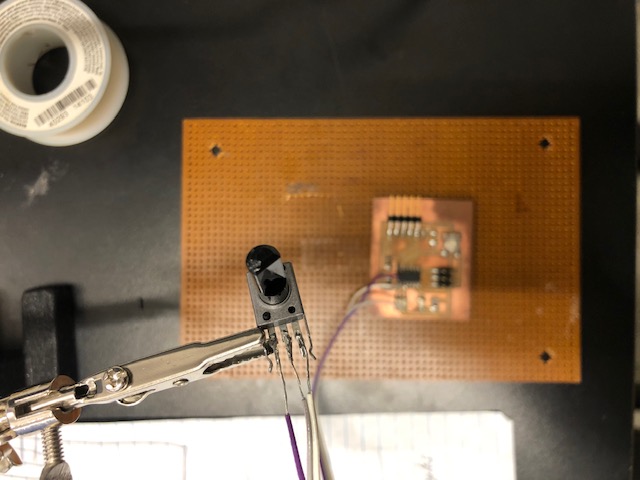
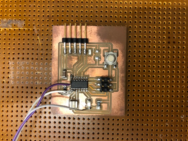
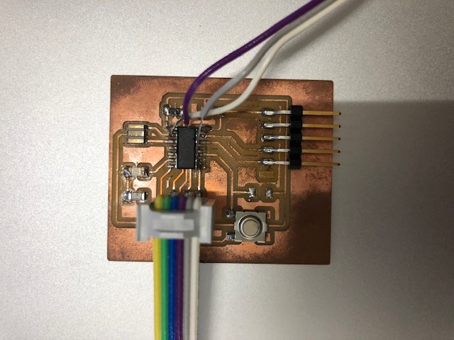
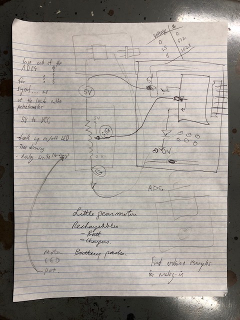
For this week's input device, I decided to begin with testing out a potentiometer, soldered onto the existing board from a couple weeks back with the ATTiny 44. Rob helped me understand how the existing board would be modified. The potentiometer has three pins. One pin goes to ground (either side), one pin goes to 5V, which is labelled VCC (voltage common collector) on the microcontroller. Lastly, the middle pin was soldered to one of the ADC's on the ATTiny44. Ideally, this setup is intended to show us the LED becoming brighter or weaker based on the potentiometer's input. Rob recommended that I search for examples for "analog-in," which immediately brought up a number of examples for analog input with use of a potentiometer on an Arduino. Rob also pointed out that we can interpret our board as quasi-arduino's… as they have most of the same functionality… though setup somewhat differently.
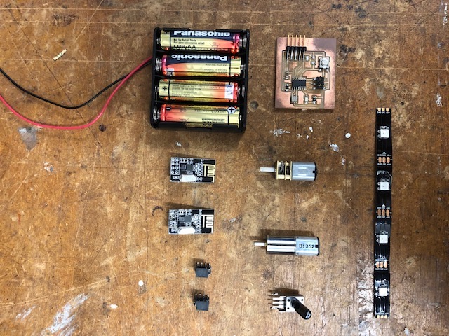
For future weeks, I've also gathered some parts for testing as time goes on. For the lighting element, I may use a light in the form of a bulb, though may instead choose the more versatile LED strip option with a custom substrate. I've also sourced a small DC gear motor from the lab, which is a High Torque 12GA 3V 30 rpm Sealed Gear Motor from Mabuchi. This can be used to wind the wire back and unwind in order to actuate the lamp. I've also sourced some radio boards for serial communication from the lab. These can be used (as an example) for hooking up a remote control to the lamp. Another option I looked at is a Bluetooth HC-05 06 Interface Base Board Serial Transceiver Module for XRFL. These bluetooth boards can be coupled with the MIT App Inventor to easily make a bluetooth on/off switch for the lamp (supposedly). This low cost part is ordered and on its way to Cambridge.
For programming, I referenced the AnalogReadSerial Code below, adjusting the values for both the LED location and input.
http://www.arduino.cc/en/Tutorial/AnalogReadSerial