Return Home
Week 2: Electronics Production
This week’s assignment was to make an in-circuit programmer by milling and programming the PCB.
I made a programmer with an ATtiny45 by following Brian’s detailed instructions.
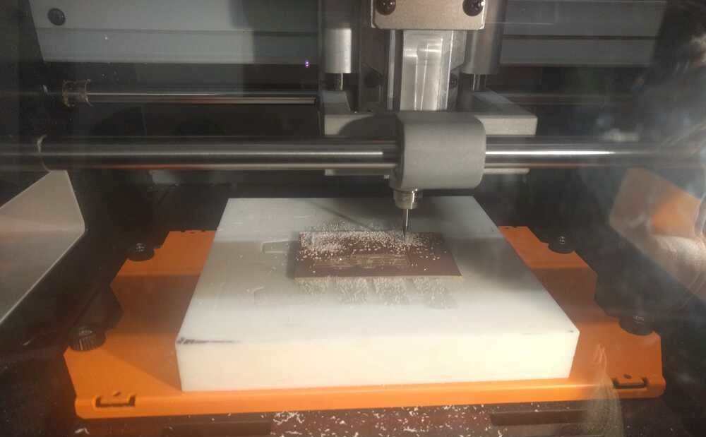
First, I milled the traces and outline cutout of the board. I followed the instructions in the lab to cut circuit boards on the Roland SRM-20. First, I had to ensure the mods were set to the right origin (make a note of X,Y, and Z). First cut the traces using the 1/64 bit (smaller), then swap with the 1/32 (larger bit) to cut the outline.
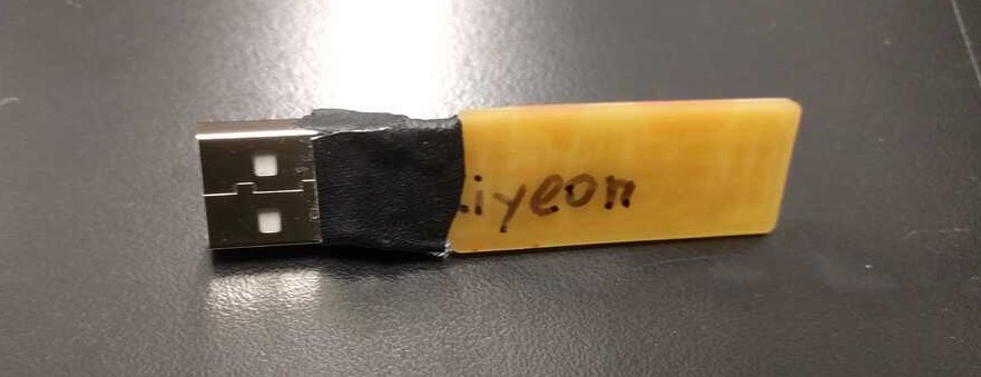
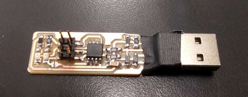
Note: if the mill does not connect with mods, turn off the mill (since it resets if the lid is opened before five seconds). Then follow instructions from beginning. Next, obtain the components (tape on an index card for ease) and solder them onto the board. To solder well, first heat the pad (board) and add some lead. Then, melt it again and add part. Ensure the Attiny45 and zener diodes are in the correct orientation. As installing the software on my laptop may be difficult, I used the Linux computer in the lab to program my board. Connect the board to the computer via an FTDI cable, ribbon cable, and a working programmer. Then, run commands on the terminal to transfer information and program my board to become a programmer. After programming, de-solder the bridge. For convenience, solder on a USB receiver and superglue and tape it (with strong tape). Now my programmer is successfully able to program things!